Click on the above “Jicheng Training“, select “Pin to Top Public Account”
120,000+ industrial control professionals follow this WeChat platform: Technical sharing, learning exchange, industrial control videos
Today, I will share some knowledge about MODBUS communication, using a touch screen to monitor inverters or instruments directly without going through a PLC: here we will take Siemens SMART 700IE touch screen and Delta VFD_M inverter as examples for introduction.
To complete such a control, we need to master the following knowledge points:
1. Select the correct communication driver in the touch screen:
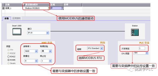
Select the Midcon MODBUS communication driver in the communication driver selection, and set the corresponding parameters in the parameter settings. These parameters need to be consistent with the settings in the inverter (data bits, parity bits, stop bits, baud rate, station number, etc.).
2. Establish variables in the touch screen:
Establishing variable addresses is extremely important. We need to convert the addresses in the information frame to the corresponding MODBUS register information addresses (the touch screen only recognizes MODBUS register information addresses, not the data addresses in the information frame, so conversion is necessary). To establish variable addresses, we need to understand the following knowledge:
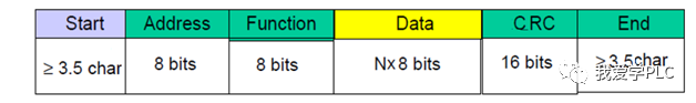
(1) The information frame format of MODBUS RTU is:
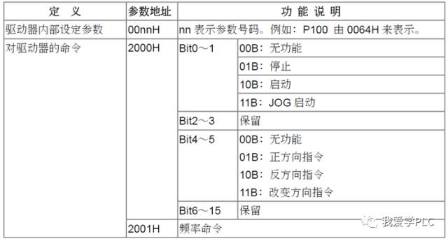
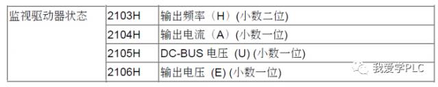
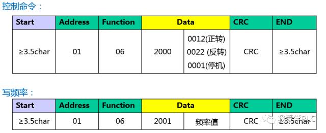
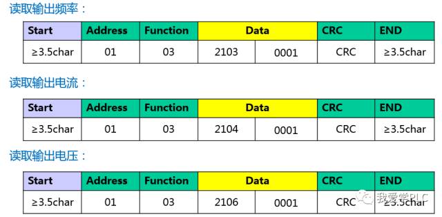
(2) Refer to the inverter’s manual for the operational commands, frequency settings, and the data addresses for reading frequency, output voltage, and current:
(3) The corresponding information frame format is as follows:
(4) The correspondence between information frame data addresses and MODBUS register addresses
The MODBUS register information addresses can be divided into four types based on the function codes: 0XXX, 1XXXX, 3XXXX, 4XXXX. Therefore, we need to convert the data information frame addresses to the corresponding MODBUS register addresses (Note: Different touch screens may define these addresses differently; for example, Weilin touch screens may add 5XXXX and 6XXXX types in their MODBUS address definitions)
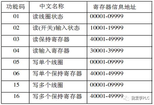
For the inverter, if you need to perform read/write functions, the main function codes used are 06 and 03 (Note: You can check the specific read/write function codes in the inverter’s communication manual)
From the above image, it can be seen that the starting address of the MODBUS register information address is 0001 (decimal). The information frame address starts from 0000H (hexadecimal), so we can obtain the following addresses:
Control command: 2000H corresponds to MODBUS information address48193 (4 indicates type: corresponding to function codes 03/06)
Set frequency: 2001H corresponds toMODBUS information address48194
Read output frequency: 2103H corresponds to MODBUS information address48452
Read output current: 2104H corresponds to MODBUS information address48453
Read output voltage: 2106H corresponds to MODBUS information address48455
(5) Establish variable addresses in the touch screen
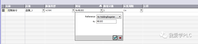
Establish the remaining variable addresses in the same way
(To be continued…)
Watch once, share once!
ClickRead the original text to learn about electrical engineering, PLC, inverter servo, CNC robots, and other knowledge
↓↓↓