Hi guys, due to personal study and work reasons, I have been silent for more than half a year. Finally, I have a break from my busy schedule, and today Robert Xiang is back to meet everyone!
A while ago, many netizens emailed me asking about the Modbus communication in Elmo’s Platinum Maestro motion controller. Today, let’s systematically discuss this topic together. (Warning: Many images ahead)
01
Talking About Modbus
First, let’s clarify what Modbus is. It is essentially an industrial field bus protocol standard, belonging to the application layer message transmission protocol, which includes three message types: ASCII, RTU, and TCP. For devices connected to the Modbus bus, they can be divided into master (poll) and slave (slave). When using TCP communication, the master is the client side, which actively establishes the connection; the slave is the server side, waiting for a connection. (Complaining: This relationship can really be confusing!)
The most common question I receive in emails is how Modbus achieves communication and what the difference is between it and EtherCAT. I think this question arises because, in our commonly used servo systems, the driver and controller typically use the EtherCAT bus.
Let’s briefly clarify this. Taking the Gold series EtherCAT driver and PMAS controller as an example, it is clear that the communication method between the driver and controller is EtherCAT. Another commonly used bus protocol is CANOpen, depending on which protocol the device supports. Then, regarding the communication between the motion controller and the host computer, the one I personally use most often is Modbus TCP, and of course, TCP/IP is also supported in PMAS. Now, you should have guessed the difference between the two: the EtherCAT bus is mainly aimed at motion control, thus focusing more on real-time performance, while Modbus TCP is generally only used for reading and operating regular I/O and non-real-time data, so this is the main difference between the two.
For debugging Modbus communication, two debugging software are essential: Modbus Poll and Modbus Slave. In Modbus TCP, Modbus Poll acts as the client to request data, while Modbus Slave acts as the server to process the requests. In the following text, we will use Modbus Poll to simulate the host computer.
02
Data Storage Issues
Any protocol usage involves filling out data packets, and Modbus is no exception. We must clarify that regardless of what data it is, it is represented as binary 01 in memory; we just read it out in different ways, which involves the difference between floating-point and integer data storage. Interested readers can search for this online.
Modbus also involves the concept of a “register.” A register is 8 bits, so for storing a float data type, we need to split it into four registers. Now the question arises again, this will involve an endianness storage issue and data transmission byte order issues. We will directly provide the conclusion: the Platinum Maestro motion controller is based on the ARM architecture, so it uses little-endian storage.
PCs typically use little-endian, so there’s no need to worry about endianness conversion issues.
Next, let’s look at the definition of the Modbus data structure in PMAS.
typedef struct{ int startRef; int refCnt; short regArr[MODBUS_IPC_WRITE_VALUES]; }MMC_MODBUSWRITEHOLDINGREGISTERSTABLE_IN;From the above definition, we can see that the regArr array is of short type (16 bits), so we need to split the float type (32) number into two 16-bit values and convert them to short type to assign to the register, and we cannot have any loss of precision. In other words, we need to split the float type data into two 16-bit values without any precision loss.
This depends on your understanding of pointers!
To reiterate, in PMAS, we can simply think of this series of Modbus registers as pre-defined arrays. The transmission of Modbus data is achieved through reading and writing these arrays, which are encapsulated within the corresponding structures in PMAS. For specifics, refer to the PMAS API manual.
Note: The Platinum Maestro controller can have up to 131070 registers, capable of holding 65536 float data (index number 0-65535).
03
Using Modbus in PMAS Controller
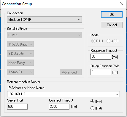
The default IP for the Platinum Maestro motion controller is: 192.168.1.3
The default Port is: 502
After installing the MDS IDE, there will be several small examples in the installation directory C:\GMAS\GMASSamples, and the project CPP_EthercatCyclicPosHome includes the use of Modbus TCP.
Since we have examples, today we will not focus on usage but rather on points that need attention: the byte order issue during Modbus transmission.
First, let’s check the correspondence between the registers of the Platinum Maestro and the simulated end registers.
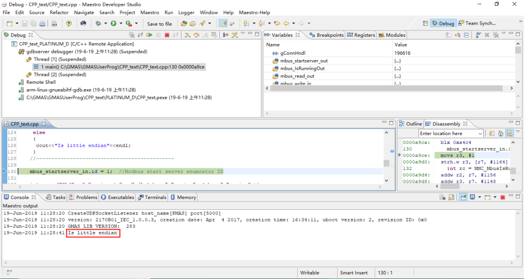
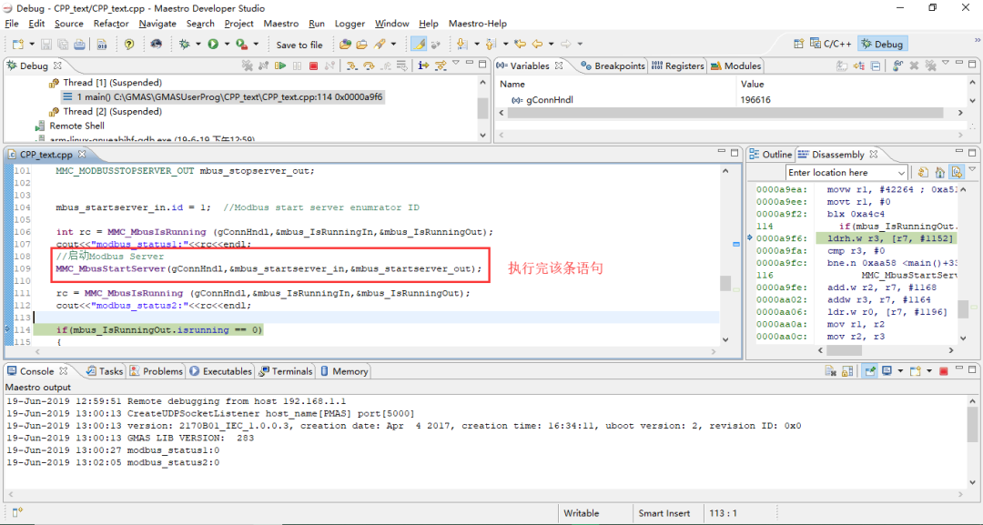
Open the control program and step through to start the Modbus Server:
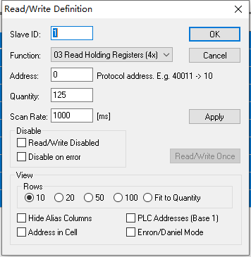
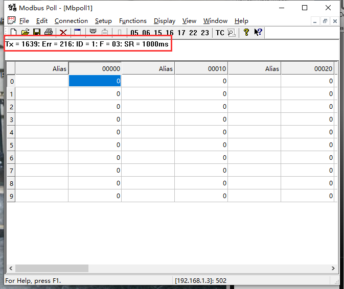
Then open Modbus Poll and add several registers:
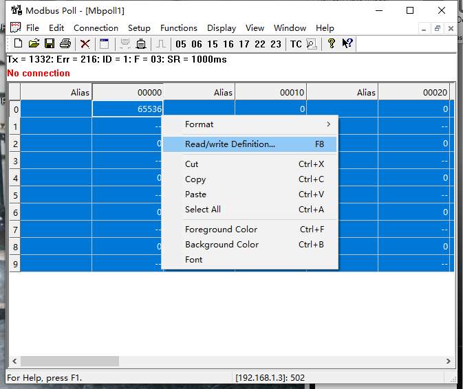
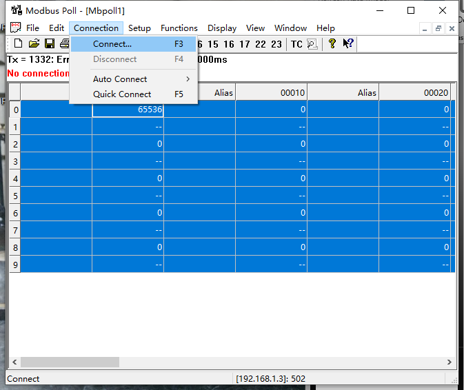
Connect to the Platinum Maestro:
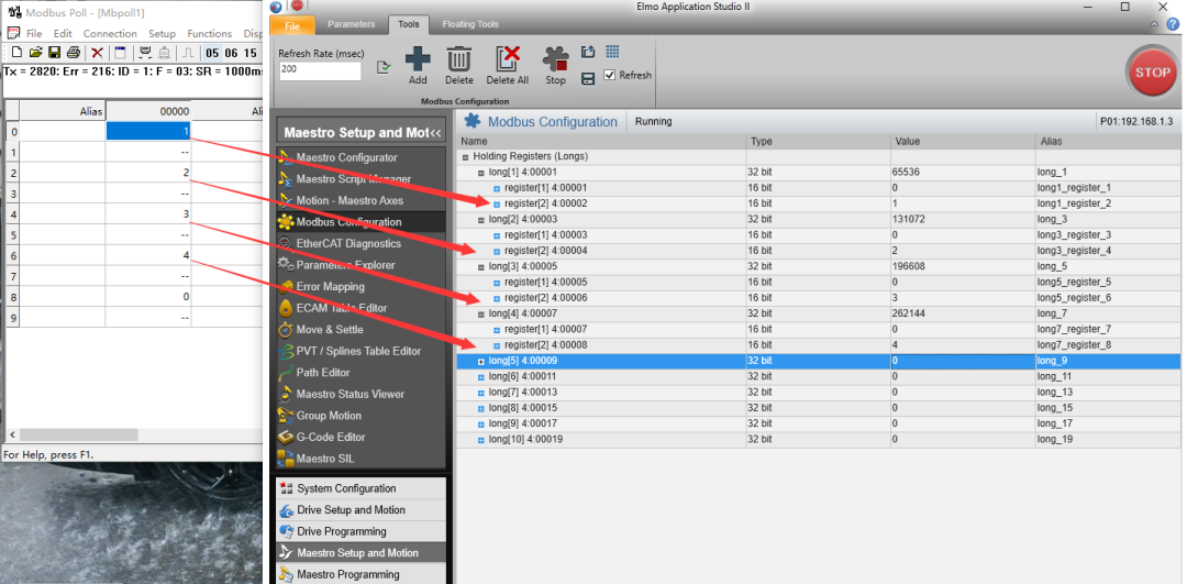
In the Modbus Configuration option of Maestro Setup and Motion in EAS II, add the register display area from PMAS:
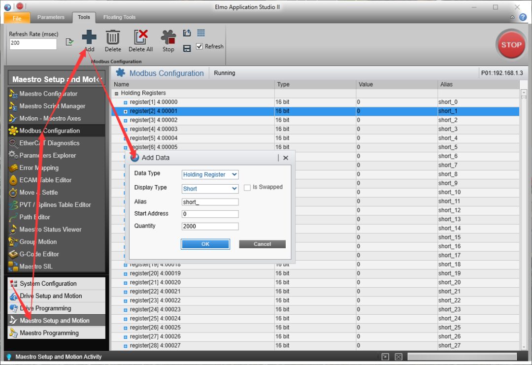
Finding that register[1]4:00000 corresponds to an invalid register; after entering the number, it will automatically disappear, mapping is invalid!!!
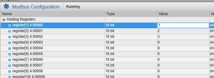
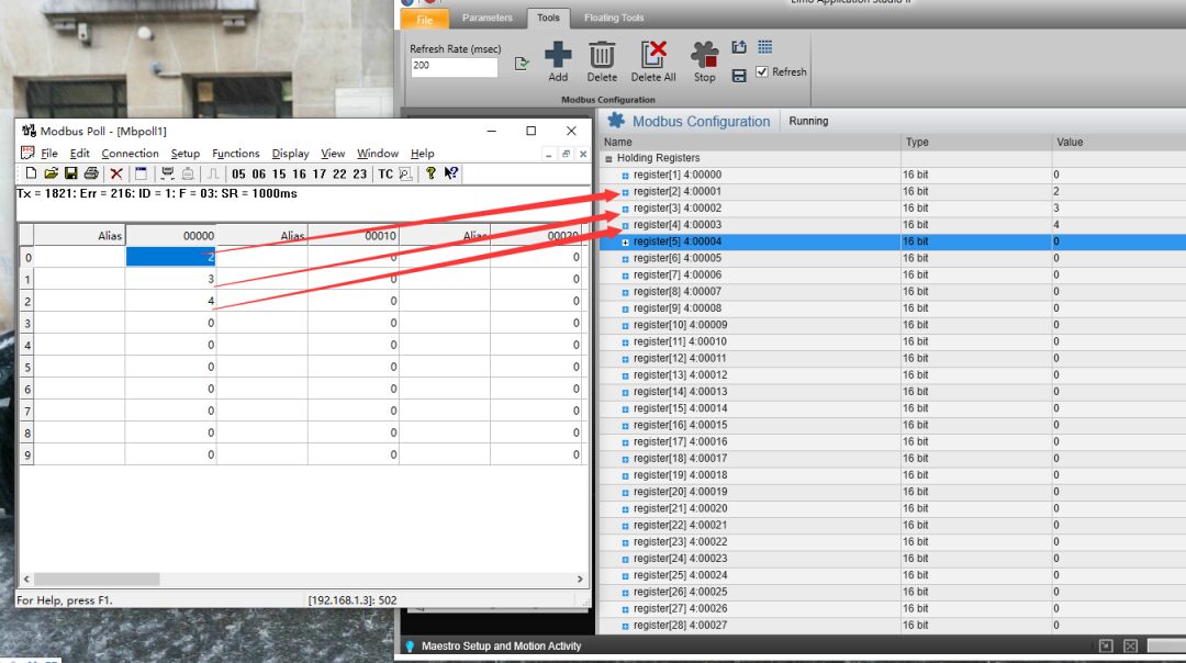
This indicates that in the Platinum Maestro motion controller, the register corresponding to the starting index 0 is invalid. The register at address index 0 in Modbus Poll corresponds to the register at starting index 1 in Maestro, and so on.
Note 1: To avoid errors, it is not recommended to start using registers from the Maestro with address index 0, as this may cause data errors. However, the register corresponding to 4:00001 can still be used, but care should be taken to avoid combining it with 4:00000 to form 32-bit or 64-bit data, as this may lead to a loss of 16 bits of data).
Note 2: When writing controller programs in MDS, the address index 0 corresponds to 4:00001 in EASII.
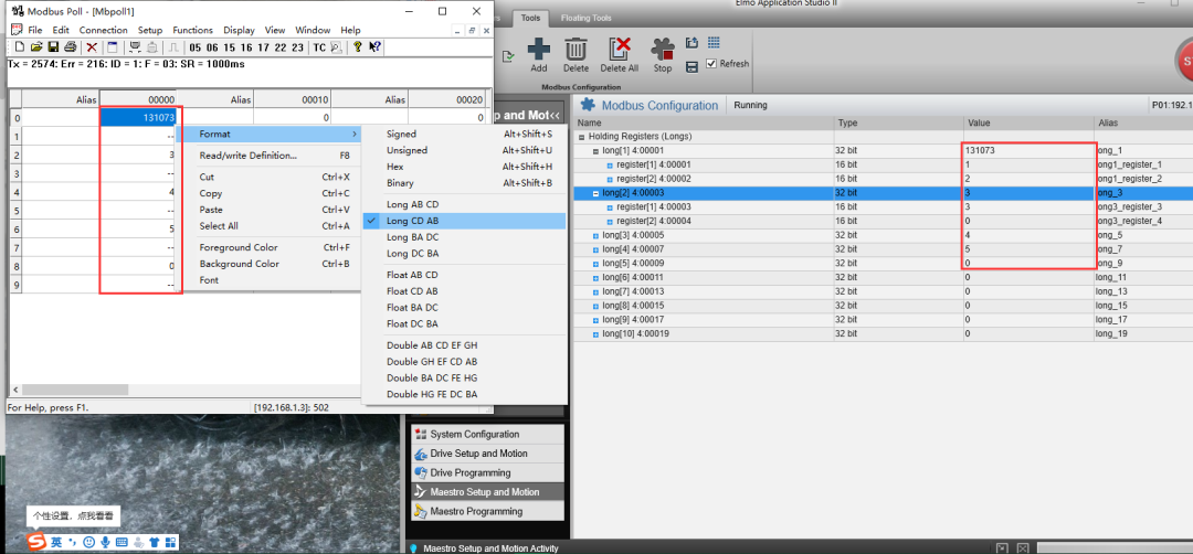
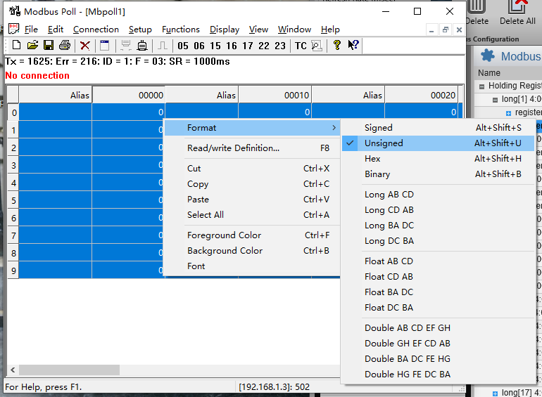
For long data types, when Maestro writes to the Modbus registers in big-endian format, the Modbus Poll side needs to parse it in little-endian format (Long CD AB). When the Modbus Poll side parses in big-endian format (Long AB CD), the correspondence with Maestro’s Modbus registers is shown in the following image. If the host computer parses in this way, then Maestro needs to convert the data storage order.
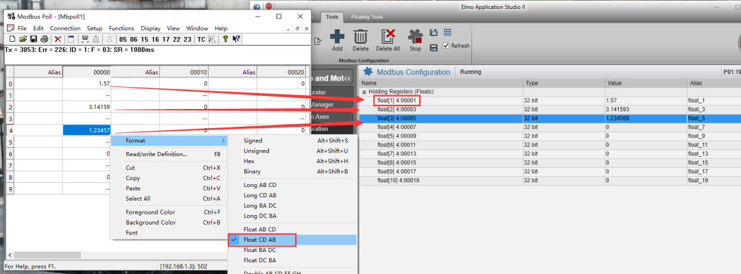
For floating-point numbers: Similarly to long, if the data in the controller is stored in big-endian (float AB CD) (this refers to the macro level of endianness, meaning the byte order when using two 16-bit registers to represent a 32-bit number, not the machine’s own storage method), then Modbus Poll should interpret it in little-endian (float CD AB); if the data in the controller is stored in little-endian (float CD AB), then Modbus Poll should interpret it in big-endian (float AB CD).
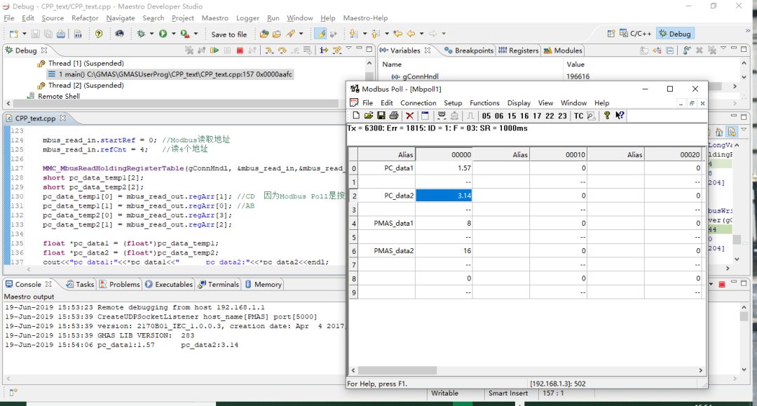
// PMAS reads the data written to the register by the PC mbus_read_in.startRef = 1; //Modbus read address starts from 4:00001 mbus_read_in.refCnt = 4; //Read 4 addresses MMC_MbusReadHoldingRegisterTable(gConnHndl, &mbus_read_in,&mbus_read_out); int pc_data1 = mbus_read_out.regArr[1]<<16 | mbus_read_out.regArr[0]; int pc_data2 = mbus_read_out.regArr[3]<<16 | mbus_read_out.regArr[2]; cout<<"pc_data1:"<<pc_data1<<" pc_data2:"<<pc_data2<<endl;Understanding this point is crucial for ensuring the correctness of your data transmission!!!!
For the Power PMAC controller, there is also this phenomenon of big-endian data being read as little-endian and little-endian data being read as big-endian.
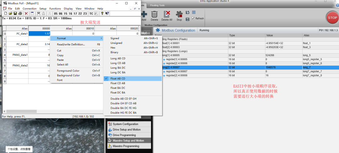
In summary, the byte order correspondence between PMAS and Modbus Poll is as follows:

Finally, here’s the test code:
int main(){ MMC_CONNECT_HNDL gConnHndl ; // Connection Handle CMMCConnection cConn ; gConnHndl = cConn.ConnectIPCEx(0x7fffffff,(MMC_MB_CLBK)CallbackFunc); cConn.RegisterEventCallback(MMCPP_MODBUS_WRITE,(void*)ModbusWrite_Received) ; MMC_MODBUSSTARTSERVER_IN mbus_startserver_in; MMC_MODBUSSTARTSERVER_OUT mbus_startserver_out; MMC_MODBUSISRUNNING_IN mbus_IsRunningIn ; MMC_MODBUSISRUNNING_OUT mbus_IsRunningOut ; MMC_MODBUSREADHOLDINGREGISTERSTABLE_IN mbus_read_in; MMC_MODBUSREADHOLDINGREGISTERSTABLE_OUT mbus_read_out; MMC_MODBUSWRITEHOLDINGREGISTERSTABLE_IN mbus_write_in; MMC_MODBUSWRITEHOLDINGREGISTERSTABLE_OUT mbus_write_out; MMC_MODBUSSTOPSERVER_IN mbus_stopserver_in; MMC_MODBUSSTOPSERVER_OUT mbus_stopserver_out; mbus_startserver_in.id = 1; //Modbus start server enumerator ID int rc = MMC_MbusIsRunning (gConnHndl,&mbus_IsRunningIn,&mbus_IsRunningOut); //cout<<"modbus_status1:"<<rc<<endl; //Start Modbus Server MMC_MbusStartServer(gConnHndl,&mbus_startserver_in,&mbus_startserver_out); rc = MMC_MbusIsRunning (gConnHndl,&mbus_IsRunningIn,&mbus_IsRunningOut); //cout<<"modbus_status2:"<<rc<<endl; if(mbus_IsRunningOut.isrunning == 0) { MMC_MbusStartServer(gConnHndl,&mbus_startserver_in,&mbus_startserver_out); int rc_t = MMC_MbusIsRunning (gConnHndl,&mbus_IsRunningIn,&mbus_IsRunningOut); if(rc_t != 1) cout<<"modbus connect error!!!"<<endl; }//------------------------------------------------------------------------------------ mbus_read_in.startRef = 0; //Modbus read address mbus_read_in.refCnt = 4; //Read 4 addresses MMC_MbusReadHoldingRegisterTable(gConnHndl, &mbus_read_in,&mbus_read_out); short pc_data_temp1[2]; short pc_data_temp2[2]; pc_data_temp1[0] = mbus_read_out.regArr[1]; //CD Because Modbus Poll sends in big-endian (ABCD) pc_data_temp1[1] = mbus_read_out.regArr[0]; //AB pc_data_temp2[0] = mbus_read_out.regArr[3]; pc_data_temp2[1] = mbus_read_out.regArr[2]; float *pc_data1 = (float*)pc_data_temp1; float *pc_data2 = (float*)pc_data_temp2; cout<<"pc_data1:"<<*pc_data1<<" pc_data2:"<<*pc_data2<<endl; int pmas_data1 = 8; int pmas_data2 = 16; mbus_write_in.startRef = 4; mbus_write_in.refCnt = 4; InsertLongVarToModbusShortArr(&mbus_write_in.regArr[0],(long) pmas_data1); InsertLongVarToModbusShortArr(&mbus_write_in.regArr[2],(long) pmas_data2); MMC_MbusWriteHoldingRegisterTable(gConnHndl, &mbus_write_in,&mbus_write_out);//------------------------------------------------------------------------------- //Close Modbus Server MMC_MbusStopServer(gConnHndl, &mbus_stopserver_in, &mbus_stopserver_out); MMC_CloseConnection(gConnHndl);}Additionally, for Modbus programming in the host computer, it is recommended to use the libmodbus library, which will not be elaborated on in this article!
04
Summary
In Modbus TCP communication, the master is the client side, and the slave is the server side;
In PMAS, we can simply think of the Modbus registers as pre-defined arrays, and the transmission of Modbus data is achieved by reading and writing these arrays;
The CDAB of the PMAS side corresponds to the ABCD of the Modbus Poll side, and the ABCD of the PMAS side corresponds to the CDAB of the Modbus Poll side;
The register index in PMAS starts from 0, while in Modbus Poll it starts from 1. Other devices should also confirm if there is this difference!
The above content is a personal summary from my engineering practice. If there are any mistakes, I welcome criticism and guidance!
Reading thousands of books also requires traveling thousands of miles. I am Robert Xiang, see you next time~
References:
https://www.cnblogs.com/ioufev/articles/10830028.html
http://miracle.blog.csdn.net/article/details/92806340

“Introduction to MuJoCo Robot Reinforcement Learning Simulation” The course will guide everyone in defining their own robots in MuJoCo, building their own controllers, writing their own reinforcement learning environments, experiencing the real training process, and enjoying the fun brought by artificial intelligence.

(Scan the QR code to view course details)