MODBUS is a very common communication method, widely used in frequency converters, servos, instruments, and PLCs due to its free nature.

Typically, PLCs act as the master station to read data from slave stations. However, the differences among various PLCs can make MODBUS programming quite complex, which can be confusing for beginners. Japanese PLCs usually implement this through ladder diagrams, similar to analog implementation, which is very cumbersome. European PLCs are simpler, using function blocks where we just fill in the parameters.
Regardless of the method, we need to write programs to implement it, and when there are too many frequency converters, timing considerations become very troublesome. Today, I will introduce Schneider PLC’s MODBUS IO SCANNER function, which makes implementing MODBUS as simple as bus communication, without programming. We will take the most cost-effective (i.e., cheapest) M218 series as an example.
1 Hardware Configuration
All M218 PLCs have two serial ports, both of which support the MODBUS protocol by default. Generally, serial port 1 is used because serial port 2 is an RJ45 interface typically connected to a touchscreen.
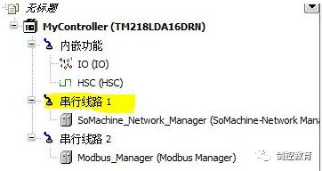
As shown in the figure, serial port 1 is in Somachine protocol mode. We will delete it by right-clicking on the serial line 1 and selecting delete. Then we will click to add.
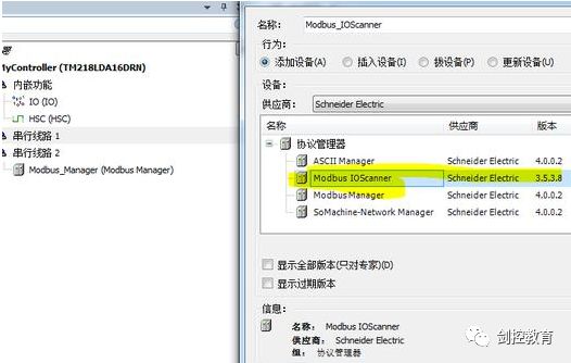
As shown above, we select Modbus IO SCANNER.
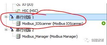
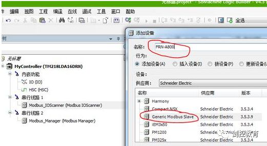
Thus, we have established a MODBUS master station. Then right-click on Modbus IO SCANNER and add Generic_Modbus_Slave, which adds a slave station.
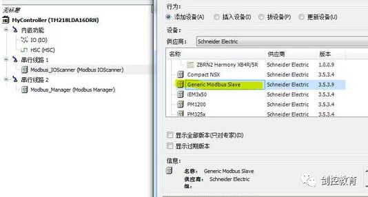
The other options in the figure, such as ZBRN2 PM1200, are Schneider power distribution products, such as frame circuit breakers, molded case circuit breakers, energy meters, etc. The Generic_Modbus_Slave we added is a general MODBUS slave, such as third-party frequency converters, and other instruments. You can think of it as the difference between bus communication with and without an EDS file. If we want to communicate with multiple slave stations, we can add multiple, and the system will automatically allocate timing without needing to program ourselves.
Of course, we can rename the Generic_Modbus_Slave to the name of our slave, for example, if we are communicating with a Mitsubishi frequency converter, we can rename it as Mitsubishi frequency converter. Unfortunately, Chinese names are not supported. However, we can rename it to the model of the frequency converter, such as FRN-A800.
2 Parameter Settings
Double-click on serial line 1 to open the parameter settings page.
Here, we set the main parameters for MODBUS communication, including baud rate, parity, etc.
3 Configuring Communication Data
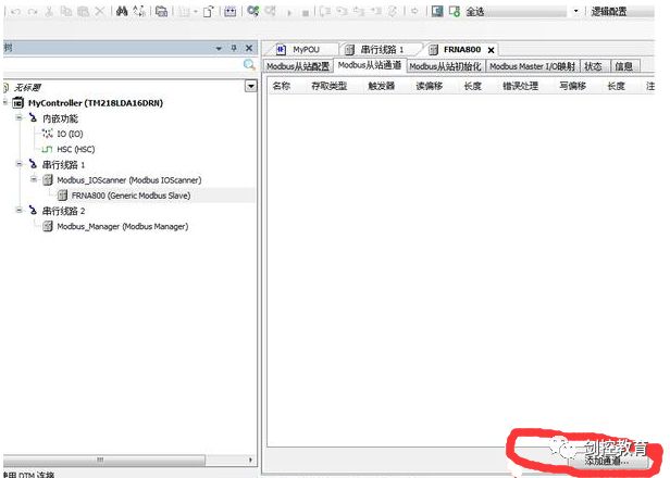
Double-click on FRNA800, which is the slave we added.

Click to add a channel.
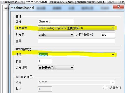
Here, we just need to add the type and address of the slave we need to read. For addresses and function codes, you can refer to the relevant programming manual. Here, let’s assume we write to 40001,
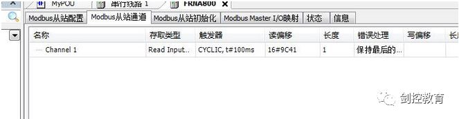
thus adding a read data channel, which is a MODBUS communication channel Channel1.
We can also give this written value a name, which is the variable name, making it easier for us to write programs. Click on Modbus Master IO mapping, and we can see the newly established Channel1.
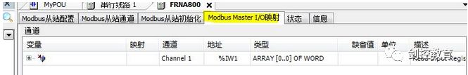
We can see that the system has automatically assigned the address %IW1, and its variable is blank. We can click on it to name it. Unfortunately, Chinese variable names are not supported here, so we establish a variable W_Fre.
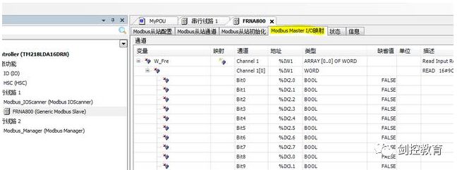
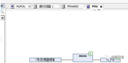
Thus, we have completed the communication settings. By assigning a value to the variable W_Fre in the program, it is equivalent to writing a value to the address 40001 of the slave. Isn’t it very convenient? No programming is needed to achieve MODBUS communication.
4 Error Handling
When an error occurs at the slave, the system will not automatically reset, causing communication interruption. We need to write a communication handling program to achieve automatic reset.
At this point, we need to call a system function, which is automatically assigned by the PLC for our MODBUS slave.

As shown, when an error occurs, it will automatically reset.
(Source: This article is adapted from