Overview of MODBUS TCP Communication with S7-1200 Integrated PN Interface
Modbus TCP is a standard network communication protocol that communicates via TCP/IP through the PN interface on the CPU, eliminating the need for additional communication hardware modules. Modbus TCP uses open user communication connections as the communication path, supporting a maximum of 8 hybrid client and server connections as allowed by the CPU’s maximum open user communication connections.
Starting from software STEP7 V11 SP1, S7-1200 CPU from Firmware V1.0.2 onwards no longer requires the installation of Modbus TCP library files, and can directly call the Modbus TCP library instructions “MB_CLIENT” and “MB_SERVER” to implement Modbus TCP communication functions, as shown in Figure 1.
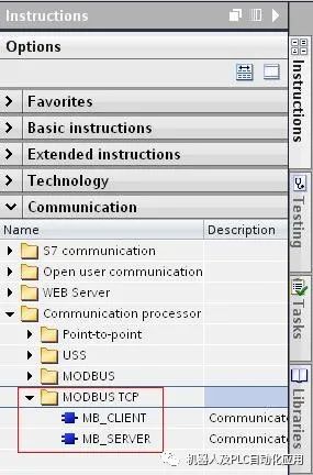
Figure 1. Modbus TCP Library Instructions
S7-1200 as Modbus TCP Server
The “MB_SERVER” instruction handles connection requests from Modbus TCP clients, receives requests for Modbus functions, and sends responses.
1. Call the MB_SERVER communication instruction in the main program “Program blocks” > “OB1”, setting connection ID, IP port, and other parameters, as shown in Figure 2.
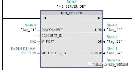
Figure 2. Calling MB_SERVER Communication Instruction
The meaning of the function block parameters is shown in Table 5 below.
| Pin | Description |
| DISCONNECT | The “MB_SERVER” instruction establishes a passive connection with the client: 0 – establishes a communication connection with the specified IP address and port number, default is 0; 1 – disconnects the communication connection, and does not perform any other functions during the disconnection process; |
| CONNECT_ID | The ID number of the connection: each connection has a unique ID number; |
| IP_PORT IP | The port number will define the IP port number to be monitored for Modbus client connection requests, default value: 502; |
| HB_HOLD_REG | A pointer to the Modbus holding register for the “MB_SERVER” instruction: holding registers can be global DB blocks or M areas, if it is a DB block, it needs to be defined as the type “Standard and Compatible with S7-300/400”, as shown in Figure 3. The holding register contains values that the Modbus client can access via Modbus function FC03 (read), FC06 (write), and FC16 (read); |
| NDR | New data ready: 0 – no new data; 1 – new data written from the Modbus client; |
| DR | Data read: 0 – no data read; 1 – data read from the Modbus client; |
| ERROR | Error bit: 0 – no error; 1 – error occurred, see STATUS for the reason; |
| STATUS | Error code; |
Table 1. Function Block “MB_SERVER” Parameters
2. Creating the MB_DATA_PTR Data Block
Through “Program blocks” > “Add new block”, select “Data block” to create a DB block, select “Standard and Compatible with S7-300/400”, click “OK”, and define the data area as an array of 100 words, as shown in Figure 3.
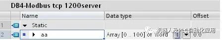

Figure 3. Creating MB_DATA_PTR Data Block
3. Correspondence of Modbus Addresses
The “MB_SERVER” instruction allows the following Modbus functions (FC01, FC02, FC04, FC05, FC15) to directly read and write access to the S7-1200 CPU’s process image input/output area (data types: BOOL and WORD), and writes incoming Modbus messages to the Modbus holding registers or reads from them via Modbus function codes (FC03, FC06, and FC16) (specified by the parameter “MB_HOLD_REG” of the MB_SERVER instruction). The size of the holding register (MB_HOLD_REG parameter) must be greater than 1 byte, detailed reference in Table 2.
| Modbus Function | S7-1200 | ||||
| Code | Function | Data Area | Address Space | Data Area | CPU Address |
| FC01 | Read: Bit | Output | 00001 to 08192 | Process Image Output | Q0.0 to Q1023.7 |
| FC02 | Read: Bit | Input | 10001 to 18192 | Process Image Input | I0.0 to I1023.7 |
| FC04 | Read: Word | Input | 30001 to 30512 | Process Image Input | IW0 to IW1022 |
| FC05 | Write: Bit | Output | 00001 to 08192 | Process Image Output | Q0.0 to Q1023.7 |
| FC15 | Write Multiple: Bit | Output | 00001 to 08192 | Process Image Output | Q0.0 to Q1023.7 |
Table 2. Correspondence of Modbus Addresses
4. Client-Side Modscan32 Software Settings
 Note: The client uses Modscan32 software for testing. Modscan32 is a third-party software for Modbus TCP Client testing, which can be downloaded from the internet.
Set the test computer’s IP address to 192.168.0.210, open the Modscan32 software, and set the function code, starting address, length, etc. in “Setup->Data Definition”, as shown in Figure 4.
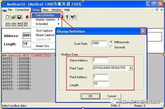
Figure 4. Setting “Data Definition” Parameters
In “Connection->connect…”, open the connection properties dialog, select “Remote Modbus TCP Server”, and set the server’s IP address and port number, as shown in Figure 5.

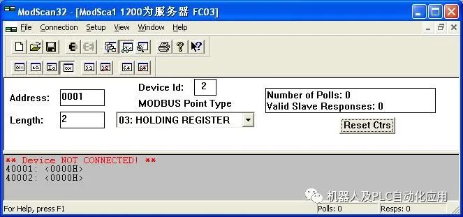
Figure 5. Setting Connection Properties
 Note: Using Modscan32 as a client does not require considering the consistency of Device ID with the server; the server automatically responds to the client’s Device ID.
5. Communication Testing
S7-1200 acts as the server, and the Modscan32 client uses FC03 function code to read two words from the server, setting the corresponding parameters of the client and server such as functions, starting addresses, and ports, as shown in Figures 5-6.
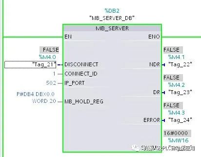
Figure 6. S7-1200 as Server
The communication result is shown in Figure 7, where Modscan32 reads the data 10 and 20 into the client’s DB4.DBW0 and DB4.DBW2 areas from the server.
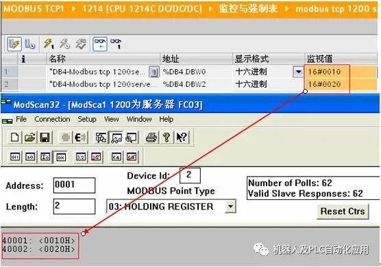
Figure 7. FC03 Communication Result
Using function FC15 to write 8 bits of data to the server’s Q0.0~Q0.7, setting connection parameters, the results are shown in Figure 8.
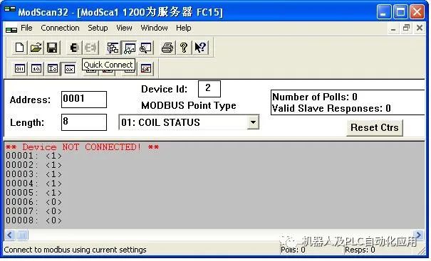
Figure 8. Using FC15 Communication, Setting Modscan32
The test result shows that the server side directly corresponds to the process image output area, 00001~00008 corresponds to Q0.0~Q0.7, as shown in Figure 9.
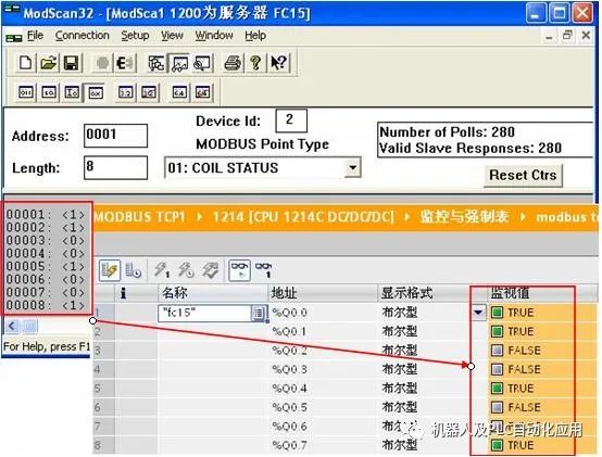
Figure 9. Using FC15 Communication Test Result
6. HR_Start_Offset Background Parameter
HR_Start_Offset is a word type used to specify the starting address of the Modbus holding register, stored in the MB_SERVER background data block, with a default value of 0, which can be written to HR_Start_Offset through programming. Taking the example of reading 2 words with the above FC03 function, set the HR_Start_Offset offset to 2, keeping other parameters unchanged, the correspondence of addresses before and after the HR_Start_Offset offset is shown in Table 7, with programming calls and results as shown in Figures 10-11.
| HR_Start_Offset | Address | Data1 | Data2 |
| 0 | Modbus Address (Word) | 40001 | 40002 |
| S7-1200 Address | DB4.DBW0 | DB4.DBW2 | |
| 2 | Modbus Address (Word) | 40003 | 40004 |
| S7-1200 Address | DB4.DBW0 | DB4.DBW2 |
Table 3. Correspondence of Addresses Before and After HR_Start_Offset Offset
The programming call is shown in Figure 10.

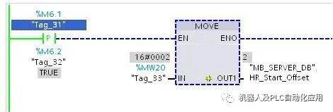
Figure 10. Setting the HR_Start_Offset Offset
The communication result is shown in Figure 11.
Figure 11. Communication Result
7. Querying the STATUS Parameter of MB_SERVER, refer to the list below Table 4.
| STATUS (W#16#) | Response Code Sent to Modbus Client (B#16#) | Error Description |
| 7001 | MB_SERVER is waiting for the Modbus client to connect to the specified TCP port, this code is reported only when the connection or disconnection operation is executed for the first time | |
| 7002 | MB_SERVER is waiting for the Modbus client to connect to the specified TCP port, this code will be reported for any subsequent executions while waiting for the connection or disconnection operation to complete | |
| 7003 | The disconnection operation has been successfully completed (valid only within one PLC scan cycle) | |
| 8187 | The pointer in parameter MB_HOLD_REG is invalid, the data area is too small | |
| 818C | The parameter MB_HOLD_REG points to an optimized area (must be “Standard and Compatible with S7-300/400” DB or M area) or an error occurred due to execution timeout (55 seconds) | |
| 8381 | 01 | This function code is not supported |
| 8382 | 03 | Data length error |
| 8383 | 02 | Data address error or accessed an area outside the holding register (MB_HOLD_REG parameter) |
| 8384 | 03 | Data value error |
| 8385 | 03 | This data diagnostic code value is not supported (function FC08) |
Table 4. STATUS Parameter of MB_SERVER