Click on the top ” Technical Training ” and select “Pin to Top“
Over 160,000 industrial control professionals follow this WeChat platform: technical sharing, learning exchange, industrial control videos.
First, let’s introduce the CP342-5. The CP342-5 is a PROFIBUS communication module from the S7-300 series, equipped with a PROFIBUS interface. It can function as either a master or a slave in the PROFIBUS-DP network, but cannot operate as both simultaneously. Additionally, it can only be used on the central rack of the S7-300 and cannot be placed on a distributed slave station.
1. PROFIBUS-DP System Architecture Diagram
The PROFIBUS-DP system architecture diagram is shown below. The system consists of one master and one slave.
① DP Master: CP342-5 and CPU315-2DP.
② DP Slave: ET 200M.
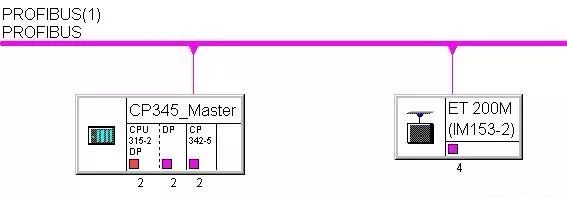
PROFIBUS-DP System Architecture Diagram
2. Configuring the DP Master
Create a new S7 project – Start STEP 7, create an S7 project, and name it “CP342-5 Master”.
Insert S7-300 workstation – Insert the S7-300 workstation and name it “CP345_Master”.
Hardware Configuration – Enter the hardware configuration window. Sequentially insert the rack Rail, power supply PS307 5A, CPU315-2DP, CP342-5, etc. When inserting CPU315-2DP, the PROFIBUS configuration interface will pop up, allowing configuration of the PROFIBUS station address. Since this example uses the CP342-5 as the DP master, no modifications are needed for the CPU315-2DP; simply click the OK button.
Set PROFIBUS Properties
Inserting the CP342-5 will also trigger the PROFIBUS configuration interface. In this example, we will set the DP station address to 2 (default value) and create a new PROFIBUS subnet, keeping the default name PROFIBUS (1).
Switch to the “Network Settings” tab, set the baud rate and line protocol; in this example, the baud rate is set to 1.5Mbps, and the line protocol is set to DP. Double-click on CP342-5 in the rack, which will bring up the CP342-5 properties dialog. Switch to the “Operating Mode” tab and select “DP master” mode, leaving the other values as default.
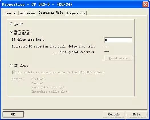
CP 342-5 Properties Window
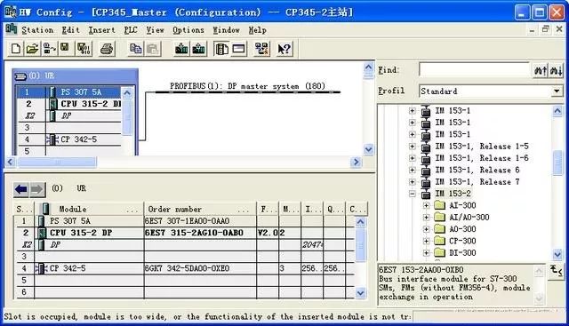
Complete the Configuration
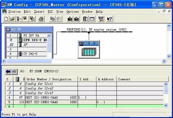
In the hardware configuration window, open the hardware catalog, navigate to “PROFIBUS-DP” → “DP V0 Slaves” → “ET 200M” subdirectory, select the interface module ET 200M (IM153-2), and drag it onto the “PROFIBUS (1): DP master system” line. Release it when the mouse turns into a + sign, and the IM153-2 properties window will pop up automatically. Set the DP station address to 4, keeping the other values as default.
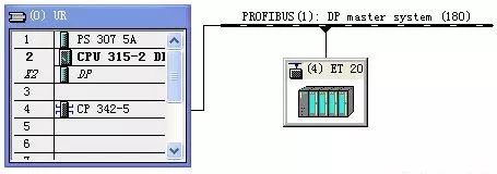
Click on the ET 200M (IM153-2) icon in the PROFIBUS system diagram to display the ET 200M (IM153-2) rack in the window below. Then, using the same configuration method as for the central rack, start from the 4th slot and sequentially insert the virtual module 16DI 6ES7 321-1BH01-0AA0 and the virtual module 16DO 6ES7 322-1BH01-0AA0 from the ET 200M (IM153-2) catalog into the ET 200M (IM153-2) rack.
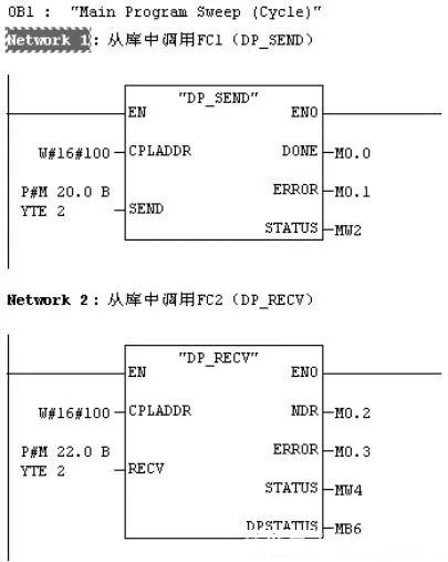
The input and output point addresses for ET 200M (IM153-2) start from 0, which is a virtual address mapping area that does not occupy the I and Q areas. The virtual address input area corresponds one-to-one with the FC1 (DP_SEND) called in the master, and the virtual address output area corresponds one-to-one with the FC2 (DP_RECV) called in the master.
Proceed with Programming
The above explanation is about the CP342-5 functioning as a master in the PROFIBUS-DP configuration. Next, we will explain the CP342-5 functioning as a slave in the PROFIBUS-DP configuration.
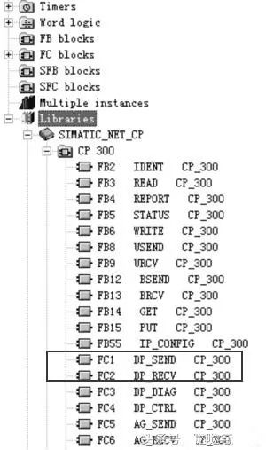
When the CP342-5 operates as a master, it needs to call FC1 and FC2 to establish the communication interface area. Similarly, when it operates as a slave, it also needs to call FC1 and FC2 to establish the communication interface area. Below, we will take CPU315-2DP as the master and CP342-5 as the slave to illustrate the application of CP342-5 as a slave. The master sends 32 bytes to the slave, and similarly, the slave sends 32 bytes back to the master.
1. PROFIBUS-DP System Structure
The PROFIBUS-DP system consists of one DP master and one DP slave:
① DP Master: CPU315-2DP;
② DP Slave: S7-300, CP342-5.
Create a new S7 project – Start STEP 7, create an S7 project, and name it “CP342-5 Slave”.
Insert S7-300 workstation – Insert the S7-300 workstation and name it “CPU315-2DP_Slave”.
Hardware Configuration – Enter the hardware configuration window, sequentially insert the rack Rail, power supply PS307 5A, CPU315-2DP, CP342-5, etc. When inserting CPU315-2DP, the PROFIBUS configuration interface will pop up, allowing configuration of the PROFIBUS station address. Since this example uses CP342-5 as the DP slave, no modifications are needed for the CPU315-2DP; simply click the save button.
Set PROFIBUS Properties
Inserting the CP342-5 will also trigger the PROFIBUS configuration interface. In this example, we will set the DP station address to 3, and create a new PROFIBUS subnet, keeping the default name PROFIBUS (1).
Switch to the “Network Settings” tab, set the baud rate to 1.5Mbps, and select DP as the line protocol. Double-click on CP342-5 in the rack, which will bring up the CP342-5 properties dialog. Switch to the “Operating Mode” tab and select “DP Slave” mode.
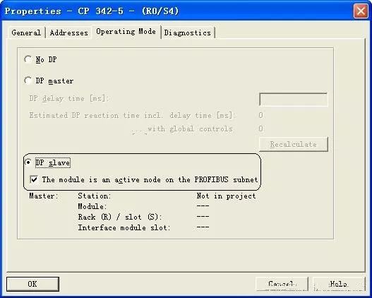
CP 342-5 Properties Window
Insert S7-300 workstation
Insert the S7-300 workstation and name it “CPU315-2DP_Master”.
Hardware Configuration
Enter the hardware configuration window. Click the icon to open the hardware catalog, and sequentially insert the rack Rail, power supply PS307 5A, CPU315-2DP, etc.
Set PROFIBUS Properties
Inserting CPU315-2DP will also trigger the PROFIBUS configuration interface, allowing configuration of the PROFIBUS station address, which is set to 2 in this example. Create a new PROFIBUS subnet, keeping the default name PROFIBUS (1). Switch to the “Network Settings” tab, set the baud rate to 1.5Mbps, and select DP as the line protocol.
Establish Communication Interface
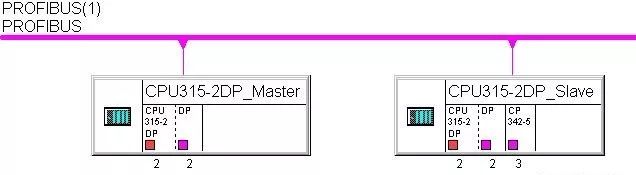
In the hardware catalog, navigate to “PROFIBUS DP” → “Configured Stations” → “S7-300 CP342-5” subdirectory, select the CP342-5 with the same order number and version number as the one in the slave, and drag it onto the “PROFIBUS (1): DP master system” line. Release it when the mouse turns into a + sign, and the already configured slave will appear in the pop-up list. Click the “Connect” button to connect the slave to the master’s PROFIBUS system.
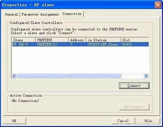
DP Slave Properties Window
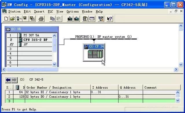
After the connection is complete, click on the DP slave, configure the communication interface area, and in the hardware catalog, navigate to “PROFIBUS DP” → “Configured Stations” → “S7-300 CP342-5” → “6GK7 342-5DA02-0XE0” → “V5.0” subdirectory, select and insert 32 bytes of input and 32 bytes of output. If you choose “Total”, the master CPU will need to call SFC14 and SFC15 to process the data packet. In this example, we choose byte communication, and no programming is needed for communication in the master.
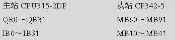
After the configuration is complete, compile, save, and download it to the CPU. You can modify the CP5611 parameters to connect to the PROFIBUS network while programming both the master and slave. The data area sent from the master to the slave is QB0~QB31, and the data area received from the slave to the master is IB0~IB31. The slave needs to call FC1 and FC2 to establish the communication area.
Complete the Establishment of the Communication Interface Area
Proceed with Slave Programming
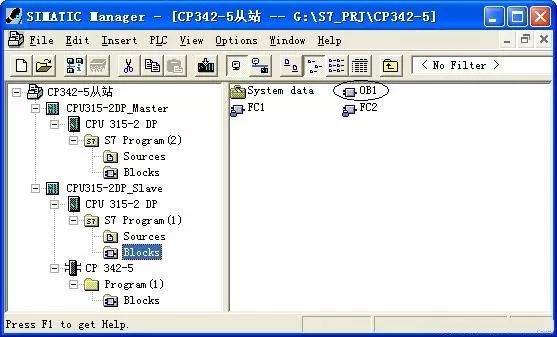
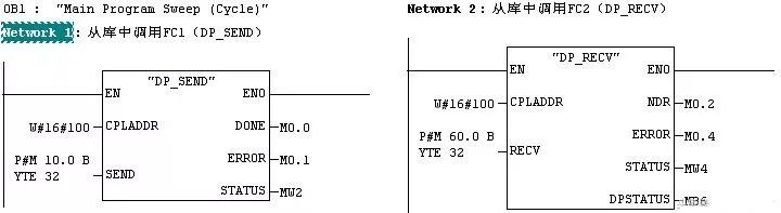
Compile, save, and download to the CPU, thereby establishing the communication interface area. The correspondence of the communication interface area is as follows:
 Reposting is a form of motivation, sharing is a virtue
Click Read Original to learn about electrical engineering, PLC, frequency servo, CNC robots, and other knowledge.