MultiSIM is a simulation tool based on Windows, launched by National Instruments (NI) Corporation, suitable for the design of board-level analog/digital circuit boards. It includes graphical input for circuit schematics and hardware description language input methods, and has rich simulation analysis capabilities.
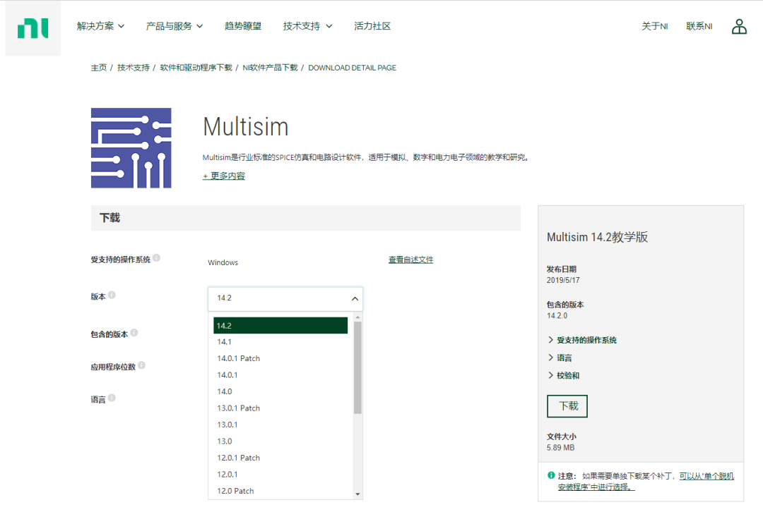
The latest version of MultiSIM is 14.2, which can be downloaded and activated directly from NI’s official website.
MultiSIM is an EDA tool for completing circuit diagram drawing and simulation in the circuit design suite, and it can be used for circuit diagram input, simulation, and exporting to subsequent steps, such as PCB output.
● User Interface
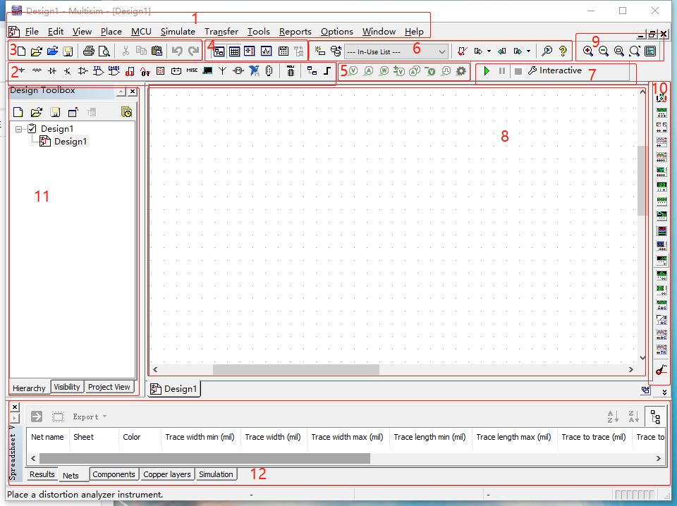
The user interface includes the following parts:
1. Menu Bar: Contains commands for all functions;
2. Component Toolbar: Contains buttons for common MultiSIM functions;
3. Standard Toolbar: Contains buttons for common functions, such as copy, cut, paste, etc.;
4. Main Toolbar: Contains buttons for common MultiSIM functions;
5. Detector Placement Toolbar: Contains buttons for various detectors;
6. In-Use Toolbar: Contains a list of components used in the design;
7. Simulation Toolbar: Contains buttons to start, stop, and pause the simulation;
8. Workspace: The area for drawing circuit diagrams;
9. View Toolbar: Contains buttons to change the display mode;
10. Instrument Toolbar: Contains buttons for each virtual instrument;
11. Design Project Window: Contains the design file name and hierarchy;
12. Spreadsheet Window: Contains Results, Nets, Components, Copper layers, and simulation information.
Operation Steps
1. Open MultiSIM. The software will automatically create a blank project file named ‘Design’.
2. Save the file to a local path and modify the file name.
In MultiSIM, you can set the auto-save feature: Options > Global options > Save > Auto-backup.
3. Place components and design the simulation circuit that needs to be verified.
4. Run the simulation, view the results measured by the measuring instruments, and analyze to draw conclusions.
● Tips During Use
Ctrl+W: Open the component library;
Alt+Y: Vertical flip;
Alt+X: Horizontal flip;
Ctrl+R: Rotate;
Press the wheel: Move the view;
Ctrl+J: Place nodes;
Ctrl+Shift+W: Place wires;
When the required components are not available in the built-in component library: download the CIR file of the component from the official website, and then use Tools > Component Wizard (select Simulation only, set the name, pins, and copy the contents of the CIR file into Model data) to add new simulation components.