Definition of LIN Bus
LIN (Local Interconnect Network) is a low-cost serial communication network designed for distributed electronic systems in automobiles.
The main function of LIN is to provide auxiliary functionality for CAN bus networks, used in places like body electronic components (such as windows, mirrors, headlights, wipers, etc.). It is suitable for applications that do not have high requirements for bandwidth, performance, or fault tolerance. Based on SCI (UART) data format, it adopts a single master controller/multiple slave devices mode, which is a special case of UART.
Features of LIN Bus
(1) The LIN bus uses a single-wire transmission form, with a bus level generally at 12V and a maximum transmission rate limited to 20kbps. Due to physical layer limitations, a LIN network can connect up to 16 nodes without arbitration.
(2) Hardware requirements are simple, requiring only a UART/SCI interface, along with a simple driver program to implement the LIN protocol.
(3) One major advantage of LIN is its low cost, with a maximum transmission rate of 20Kbps. Suggested communication rates are as follows: low-speed 2400bps, medium-speed 9600bps, high-speed 19200bps (bps stands for bits per second).
Network Topology of LIN
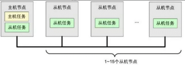
(1) Single master task, multiple slave tasks;
(2) The master node contains both master and slave tasks;
(3) The slave nodes only contain slave tasks;
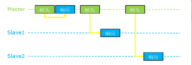
(4) The master task decides the messages on the bus, while slave tasks send data;
(5) All nodes in the LIN network (including master nodes) have slave tasks, and when they receive message information from the master task, one of them must respond to the message.

LIN Levels
(1) The LIN bus has two complementary logic levels: the dominant level (reference ground voltage) is logic 0, and the recessive level (supply voltage) is logic 1.
(2) The transmission and reception of the recessive and dominant levels ensure stable data transmission by pre-setting the voltage difference range.
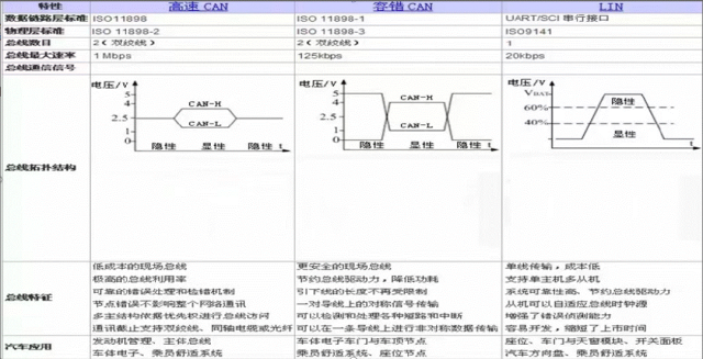
(3) The sending signal voltage must meet the conditions: recessive level > Vbat 80%, sending signal voltage must meet the dominant level < Vbat 20%.
(4) The receiving signal voltage must meet the conditions: recessive level > Vbat 60%, sending signal voltage must meet the dominant level < Vbat 40%.
Frame Structure of LIN
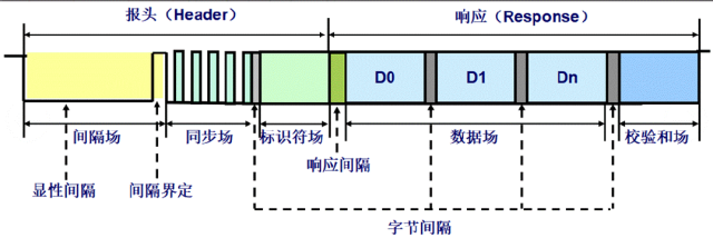
A frame in the LIN bus consists of two main parts: the message header and the message response.
The message header is sent by a master node’s master task, while the message response (hereinafter referred to as response) is sent by either a master node or a slave node’s slave task.
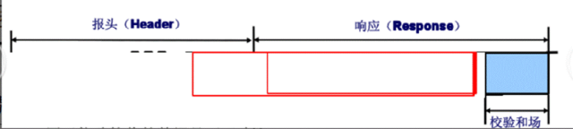
The message header consists of a synchronization interval field (minimum 13 dominant bits), a synchronization field (1 byte: 0x55), and a PID field (1 byte); the response consists of a data field of 1-8 bytes and a checksum field (1 byte).
There is a frame internal space separator between the message header and the response, with a minimum space of 0, totaling 11 bytes.
Synchronization Interval Segment
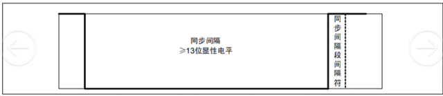
The synchronization interval segment consists of a synchronization interval (Break) and a synchronization interval delimiter (Break Delimiter):
1. The synchronization interval lasts at least 13 dominant bits and marks the beginning of a frame, sent by the master node;
2. The synchronization interval delimiter lasts at least 1 recessive bit.
3. The synchronization interval field is the only field that does not conform to the UART format.
4. A slave node needs to detect at least 11 consecutive dominant bits to consider it as an interval signal.
Synchronization Segment
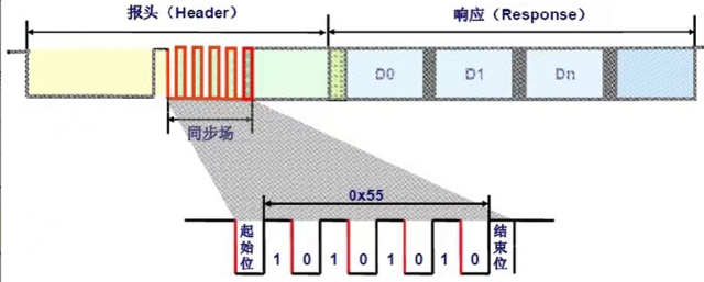
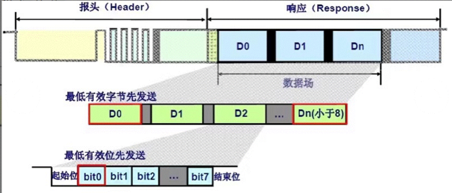
1. The synchronization segment consists of 1 start bit (dominant) + 8 data bits + 1 stop bit (recessive).
2. In a LIN frame, data transmission always sends LSB (least significant bit) first, followed by MSB (most significant bit).
3. LIN synchronization uses the falling edge bit as a marker, adopting byte 0x55 (binary 01010101b), ensuring that all slave nodes use the same baud rate as the master node to send and receive data.
Protected Segment (PID)
The first 6 bits of the protected ID segment are called Frame ID, and with two parity bits are referred to as Protected ID.
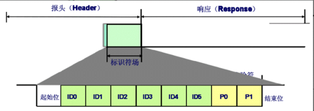
Protocols from LIN 2.0 and above use PID.
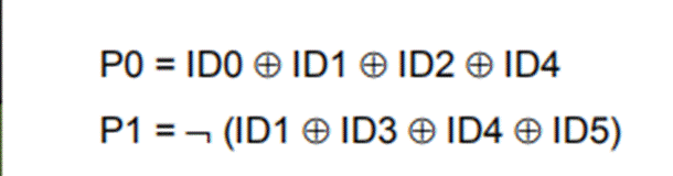
The Frame ID ranges from 0x00 to 0x3F, totaling 64 (ID:60-61 for diagnostic ID, ID:62-63 reserved), and the parity check formula is as follows:
Data Segment
The data field length is 1 to 8 bytes;
The low byte is sent first, and the low position is sent first;
If a signal length exceeds 1 byte, it is sent in a low-first manner (little-endian mode).
Checksum Segment
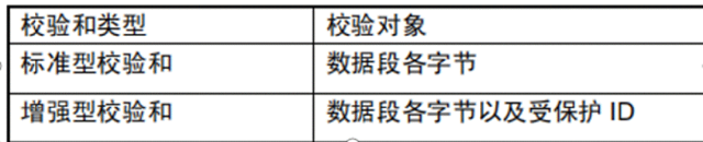
The checksum segment checks the content transmitted in the frame. Checksums can be standard or enhanced.
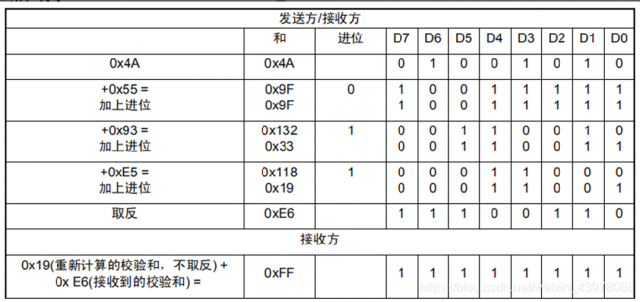
For example: using a standard checksum, Data1 = 0x4A, Data2 = 0x55, Data3 = 0x93, Data4 = 0xE5, the calculation method is as follows:
LIN Bus Waveform
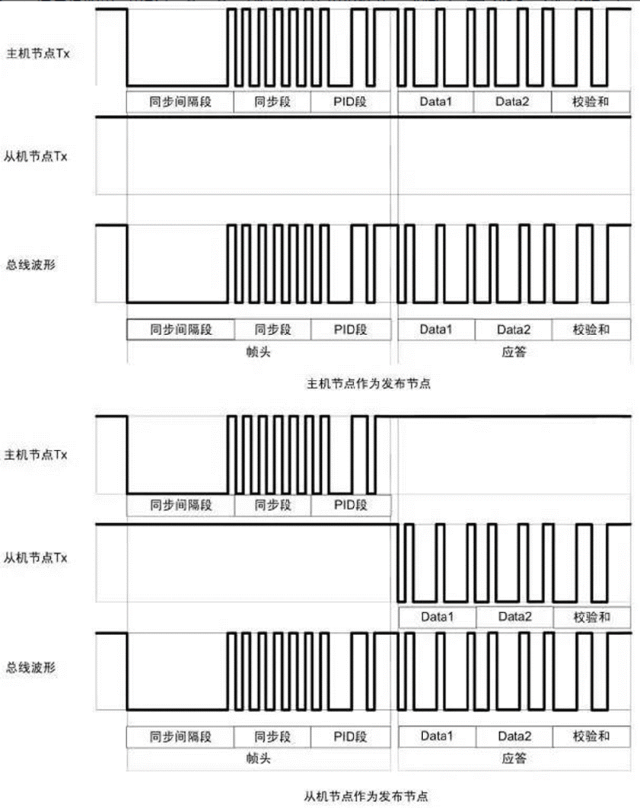
LIN Scheduling Table
(1) The scheduling table is responsible for scheduling the order of frame transmissions in the network:
Assigning sending gaps for each frame;
Sending gap: the time frame can be sent;
Different frames may have different sending gaps.
(2) The scheduling table is determined during the network system design phase, specified in the LDF file.
(3) The master task can have multiple scheduling tables and switch between different schedules.
Parsing LIN
Sending PID:0X28 Data (0-7): 0xFF 0x28 0xFF 0xFF 0xFF 0xFF 0xFF 0xFF
The oscilloscope parses LIN data:
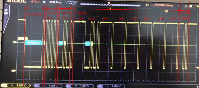
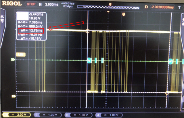
The oscilloscope parses the LIN sending cycle:
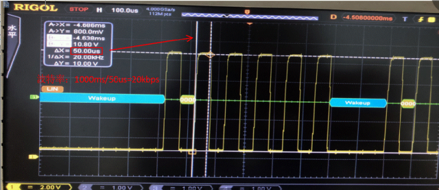
The oscilloscope parses the LIN sending baud rate (19200bps):
Data Size Endian Transmission Method
Little-endian mode is also known as Intel format
Big-endian mode is also known as Motorola format
From the figure, each line represents one byte’s 8 bits, from right to left are bit0, bit1…bit7. There are 8 lines, from top to bottom are byte0, byte1…byte7. A total of 64 bits (bit order from byte0 to byte7 increases sequentially).
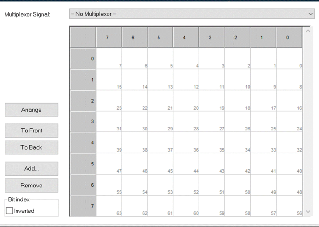
Regardless of whether using Motorola or Intel format, the only difference occurs when analyzing a single signal across bytes.
LIN Node Synchronization Mechanism
Hard Synchronization
LIN nodes are unsynchronized before communication;
To reduce costs, slave nodes generally do not use crystal oscillators but instead use RC oscillators;
Single-wire transmission does not use a clock line;
When there is no data transmission, the bus is in a recessive state;
To ensure data consistency, synchronization must occur before effective data transmission.
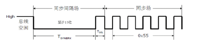
Synchronization interval field:
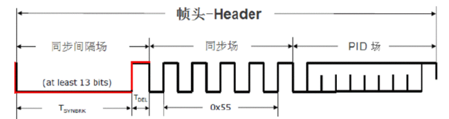
Synchronization field:
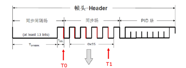
One byte, fixed structure: 0x55, used for synchronization; detects 5 falling edges: Tbit=(T1-T0)/8
Resynchronization
Uses asynchronous transmission methods
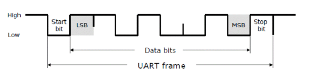
Based on UART/SCI communication format, sending one byte requires 10 bit times (Tbit).

Finally, if you have any original technical articles related to electronic design or others, feel free to submit them to us. We will select the best ones, and publishing an article will earn you a reward!

Friendly Reminder:
Due to recent changes in the WeChat public platform push rules, many readers have reported not seeing updated articles in time. According to the latest rules, it is recommended to click on “Recommended Reading, Share, Collect” more often to become a regular reader.
Recommended Reading:
-
Intel Approved to Sell Chips to Huawei! AMD Very Unhappy
-
Mass Layoffs in R&D!! Business to Withdraw from China?
-
Famous Mobile Brand to Exit China!
-
Breaking News! Changdian Acquires 80% Stake in US Storage Giant
-
Threatening Employees with Layoffs! Chip Giant’s Hidden Layoffs of 40%
Please click 【View】 to give the editor a thumbs up
