1. Introduction
UART is a universal serial data bus used for asynchronous communication. This bus supports bidirectional communication, converting parallel data into serial data for transmission when sending data, and converting received serial data back into parallel data upon reception, enabling full-duplex transmission and reception.
2. Wiring Methods
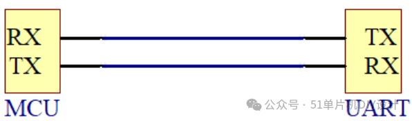
① One-to-One Communication:
Typically, UART serial communication is conducted in a one-to-one manner, where the host’s RX connects to the slave’s TX, and the host’s TX connects to the slave’s RX for communication, as shown in the diagram below.
② One-to-Many Communication:
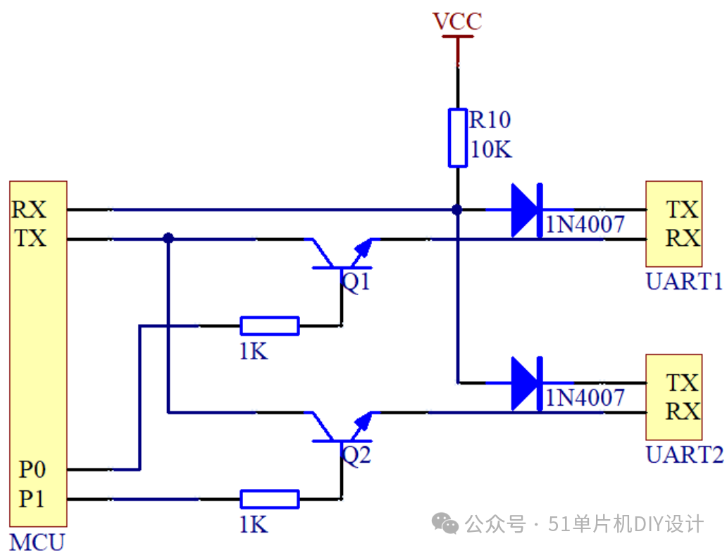
Sometimes, a microcontroller (MCU) has only one serial port, while peripheral devices use multiple serial communication protocols. If directly connected, this can lead to signal cross-interference, resulting in data transmission errors.
Since the serial port is idle at a high level and low level indicates data/start bit, the slave can send data by using diodes to build an AND gate, logically combining the TX of two slaves. Thus, when Slave 1 sends data, Slave 2 remains in an idle state (outputting 1), preventing interference with Slave 1’s transmission.
Data is sent to the specified slave through the MCU’s IO port. When we want to send data to Slave UART1, we simply set P0 to high and P1 to low. At this point, Q1 is turned on, and Q2 is turned off; thus, when the MCU’s TX outputs a low level, only Slave UART1’s RX is pulled low, while Slave UART2’s RX remains at a low level. Conversely, to send data to Slave UART2, we only need to turn on Q2 and turn off Q1. As shown in the diagram below:
3. Communication Method
The communication method of UART serial port is serial communication, sending and receiving bytes bit by bit, converting parallel data into a serial data stream for transmission, and converting the received serial data stream back into parallel data.
UART serial communication requires two signal lines: one for serial transmission and the other for serial reception.
A frame of data in UART during transmission or reception consists of four parts: start bit (low level), data bits, parity bit, and stop bit (high level).
The start bit indicates the beginning of a data frame, while the stop bit indicates the end of a data frame, and the data bits contain the valid data within a frame.
The parity bit can be either odd or even, used to check for errors in data transmission. In odd parity, the sender ensures that the total number of 1s in the data bits plus the parity bit is odd; the receiver checks the number of 1s upon receiving data, and if it is not odd, it indicates an error occurred during transmission. Similarly, even parity checks whether the number of 1s is even.
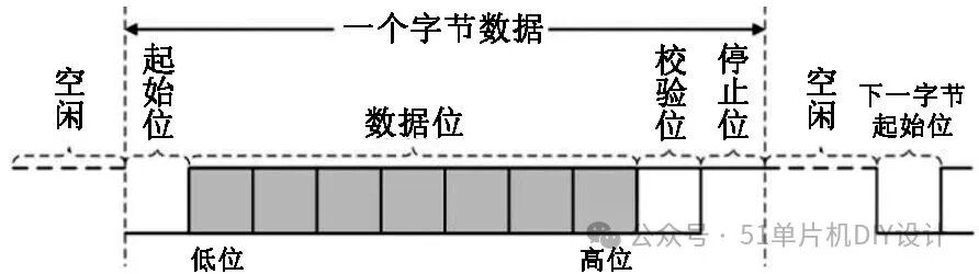
The data format and transmission rate in UART communication are configurable. The data bits can be selected as 5, 6, 7, or 8 bits (most commonly used); the parity bit can be set to odd parity, even parity, or no parity; and the stop bits can be set to 1 (default), 1.5, or 2 bits.
The baud rate represents the speed of serial communication, indicating the number of bits transmitted per second, measured in bps (bits per second). Common baud rates include 9600, 19200, 38400, 57600, and 115200.
4. Communication Process
① Sending Process:
When the rising edge of the send command is detected, data transmission is initiated. The start bit ‘0’ is sent first; then, the data bits are sent in the order of least significant bit first, followed by the parity bit calculated from the data bits, and finally the stop bit ‘1’. The specific timing is as follows:
External: Data preparation → Set send command to ‘1’;
Internal: Detect rising edge of send command → Start counter → Send start bit, data bits, parity bit, stop bit → Clear counter → Detect rising edge of send command.
② Receiving Process:
When the falling edge of the RX data line is detected, it indicates the arrival of a data packet’s start bit, initiating data reception. The start bit is received first for detection purposes; then, the data bits are received and stored in the data register. When the last data bit is received, the data read completion flag is set to ‘1’; the parity bit is then checked, and if incorrect, the data error flag is set to ‘1’; finally, the stop bit ‘1’ is received, and if incorrect, the frame error flag is set to ‘1’. The specific timing is as follows:
Internal: Detect falling edge of RX → Start counter → Receive start bit ‘0’ → Receive data bits → After receiving the last data bit, set data read completion flag to ‘1’ → Check parity bit → Receive stop bit ‘1’ → Clear counter → Detect falling edge of RX;
External: Detect rising edge of data read completion flag → Read the received data.