 1. Bus TypesThe Society of Automotive Engineers (SAE) classifies automotive networks into the following types based on data transmission speed.>>>>
Class A
Data transmission rate is 1 to 10 kbit/s, suitable for systems with low real-time requirements. The communication protocols mainly include LIN, TTP (Time-Triggered Protocol) /A, etc., and applications include central locking, power windows, electric seats, and lighting.>>>>
Class B
Data transmission rate is 10 to 125 kbit/s, with related communication protocols including CAN B (Medium-speed CAN), SAE J1850 (OBD II), VAN (Vehicle Area Network), etc. Applications include electronic vehicle information centers, fault diagnostics, and instrument information display.>>>>
Class C
Data transmission rate is 125 kbit/s to 1 Mbit/s, with related communication protocols including CAN C (High-speed CAN), TTP (Time-Triggered Protocol) /C, etc., mainly used for control of power and transmission systems.>>>>
Other Types
In addition to the above three classes, if the data transmission rate is between 1 to 10 Mbit/s, related communication protocols include FlexRay, Byteflight, supporting drive-by-wire applications. For data transmission rates above 10 Mbit/s, protocols such as D2B, MOST, IDB, etc. are used, mainly in applications like automotive navigation and multimedia entertainment systems.Additionally, based on the connection method of various nodes (control modules) in the vehicle, automotive network systems can be classified into ring, bus (BUS), and star connections.2. Bus Characteristics01Characteristics of CAN BusThe CAN bus is a bidirectional data line used for data transmission, with twisted pair cables being the most commonly used medium. Data is sent to each control unit via the CAN bus, which then processes it.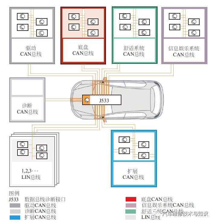 Bus System StructureTo prevent external electromagnetic interference and radiation, the CAN bus uses two wires twisted together, with opposite potentials. If one wire has a voltage of 5V, the other will have 0V, and the total voltage remains constant, causing the electromagnetic field effects to cancel each other out due to opposite polarity.This method protects the CAN bus from external electromagnetic field interference while keeping radiation neutral, i.e., no radiation.Each node (ECU) on the CAN bus has its own address, continuously monitoring the data sent over the bus to ensure the received data matches its own address.02Characteristics of LIN BusLIN (Local Interconnect Network) is a low-cost, locally interconnected serial communication network protocol, suitable for scenarios with low data transmission rate requirements.The goal of the LIN bus is to provide auxiliary functions for in-vehicle networks (like the CAN bus).The LIN bus is a single-wire bus that transmits data over one conductor.It is mainly used in anti-theft systems, adaptive headlights, xenon headlights, driver-side switch components, exterior mirrors, central locking, electric sunroofs, and HVAC blower controls.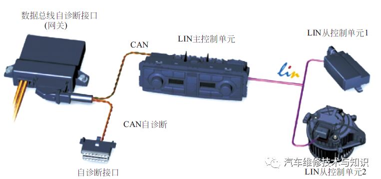
LIN Bus
03Characteristics of MOST BusMOST stands for Media Oriented Systems Transport.The MOST bus transmits data unidirectionally (closed loop) and is used in communication and infotainment domains.It is a high-speed network using optical fiber as the transmission medium, with speeds up to 25 Mbit/s, and has unique advantages in weight reduction and anti-interference.The MOST network technology structure is a ring structure, where optical signals are transmitted from one node to another. The receiving device converts the signal into an electrical signal, which is then processed by the MOST processor and finally converted back into an optical signal.For example, as shown in the figure below, the data exchange of the infotainment system control unit occurs via the MOST bus.It can achieve very high data transmission rates, such as those required for transmitting audio data.Video signals from a TV tuner, reversing camera, or DVD player are transmitted to the infotainment control unit J794 via analog video lines in FBAS signal format.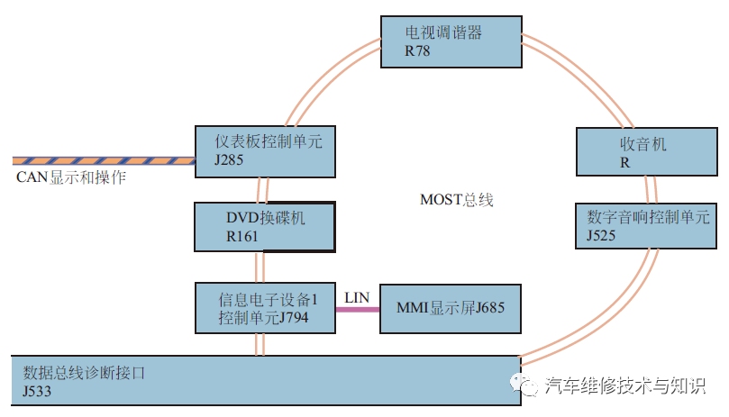 MOST Bus Ring Topology04FlexRay BusThe FlexRay bus is a dual-wire bus system with a data transmission rate of 10 Mbit/s.One wire is designated as the positive bus (pink), and the other as the negative bus (green).The FlexRay bus cannot operate in single-wire mode, as it requires analysis of the potential difference between the two wires during operation.The goal is to achieve reliable, real-time, and efficient data transmission between electrical and mechanical electronic components to meet the needs of automotive network technology.
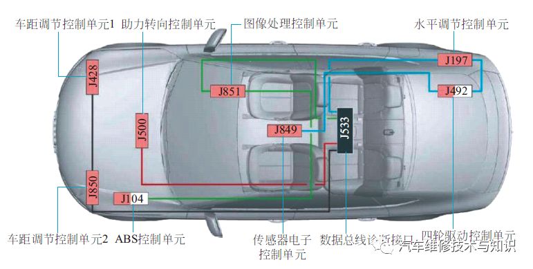 FlexRay Bus TopologyFor the FlexRay bus, its diagnostic interface acts as a controller.There are 4 FlexRay bus branches on J533, connecting 8 control units (when all equipment is equipped).Each control unit at the end of a branch is equipped with a low-resistance resistor, while the intermediate control units have a high-resistance internal resistor.Theoretically, the maximum wire length within each branch should not exceed 12m.3. Fault Characteristics of Bus Systems01 Faults Caused by Power System Issues Leading to CAN Bus FailuresThe core part of the in-vehicle network transmission system is the electronic control module (ECM) containing the communication chip. The normal operating voltage of the ECM is 10.5 to 15.0V. If the working voltage provided by the vehicle’s power system is below this value, it can cause temporary malfunctions in some ECMs with high voltage requirements, resulting in brief communication failures in the entire in-vehicle network transmission system. This phenomenon is similar to setting a diagnostic tool to check a sensor interface before starting the engine; when the engine starts, the drop in voltage causes a communication interruption, returning the diagnostic tool to its initial interface.02 Node Failures
Nodes are the electronic control modules in the in-vehicle network transmission system, so node failures refer to ECM failures, including software and hardware failures. Software failures occur when there are defects or conflicts in the transmission protocol or software program, causing communication chaos or failure in the in-vehicle network transmission system. These failures usually occur in batches and are not repairable; hardware failures generally arise from communication chip or integrated circuit failures, preventing the in-vehicle network transmission system from functioning normally. For automotive CAN bus systems using low-version information transmission protocols, if there is a node failure, the entire vehicle multiplex transmission system may become inoperative.
03 Link Failures
When the link in the in-vehicle network transmission system fails, such as short circuits, open circuits, or signal attenuation or distortion due to physical properties of the lines, multiple electronic control units may fail to operate or the control system may malfunction. To determine whether it is a link failure, an oscilloscope or a specialized automotive optical fiber diagnostic tool is typically used to observe whether the communication data signal matches the standard communication data signal, and fault detection tools can also measure the fault codes related to the bus.
4. Repair CaseFault Phenomenon:A certain old model Magotan 1.8T car cannot automatically lock.Fault Diagnosis and Inspection:(1) Execute the diagnostic tool to check the vehicle’s automatic locking function, and enable this function using guided functions, but the vehicle still cannot activate this function.(2) Enter the gateway list, as shown in the figure below, where all comfort system control units display “fault” or “unreachable”.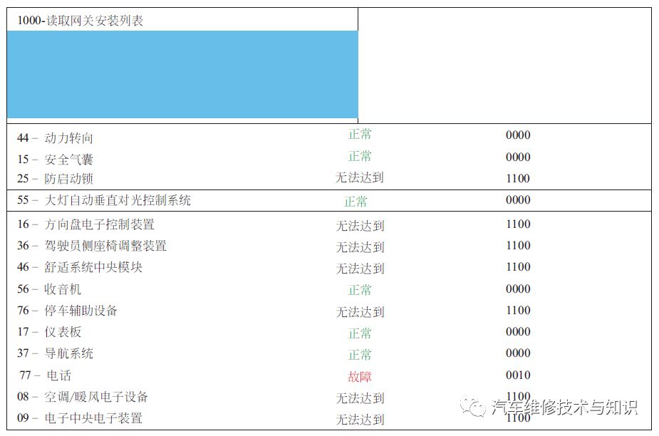 Data StreamThe diagnostic tool can individually access each control unit, but occasionally there will be a prompt indicating no response from the control unit when entering.(3) After entering the gateway, it is found that the gateway shows “Comfort system data bus is in single-wire mode/open circuit”.It should normally display “dual-wire mode”.(4) From the above data, it can be seen that the driver-side door is in single-wire mode.Remove the left front door harness connector and measure the CAN bus between the driver-side door J386 and the gateway J533, finding that the CAN-L line is open circuit.Repair the CAN-L line and recheck diagnostics, but the fault still exists, and the gateway is still in single-wire mode.(5) Remove the gateway connector again and measure the CAN bus between J533 and J386, and at this point, the connection is normal.Reinstall the gateway connector, and upon reading the data stream again, it shows normal.After shaking the gateway connector, it again shows single-wire mode, indicating a poor connection in the gateway connector or gateway.Fault Elimination:Replace the gateway and repair the comfort CAN-L line.Fault Cause Analysis:This vehicle’s fault is due to a combination of two faults; during diagnosis, repairs should first follow the prompts given by the control units. The comfort bus has a single-wire mode, and only when the gateway has a poor connection causing the comfort system to not receive the vehicle speed signal will it exhibit a fault, preventing automatic locking. end
This content is sourced from
“Automotive Electrician: From Beginner to Master” | Edited by Zhou Xiaofei | Published in November 2019
◎ This is a book suitable for automotive electricians to start and improve, covering all aspects of automotive electrical work.The first part focuses on the structural principles of major components of automotive electrical systems;the second part combines video explanations, focusing on basic knowledge and operational skills of automotive electrical maintenance.
Previous Exciting Articles↓
1. Regular Maintenance Methods for CAN Bus(1)
2. Regular Maintenance Methods for CAN Bus (2)
3. [Typical Case] Automotive Bus Fault Repair Case
4. Diagnostic Case Analysis of Buses
5. Color Illustrated Guide to the Network Bus of Pure Electric Vehicles
 Click below “Read Original” to recharge together!Everyone is watchingIt is said that those who click “Watching” are all handsome guys?!