Follow our public account, click the ” ··· ” in the top right corner of the public account homepage, set a star mark, and stay updated on the latest news in intelligent automotive electronics and software.
 Source:Embedded News Selection
CAN (Controller Area Network) is a serial communication network capable of achieving distributed real-time control.
When thinking of CAN, one must think of Bosch, the German company that developed it (along with Intel). CAN has many excellent features that allow it to be widely used. For example: a maximum transmission speed of 1 Mbps, a maximum communication distance of 10 km, a lossless arbitration mechanism, and a multi-master structure.
In recent years, the price of CAN controllers has decreased significantly, and many MCUs have integrated CAN controllers. Now, every car is equipped with a CAN bus.
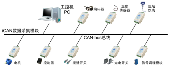
A typical application scenario of CAN:
CAN Bus Standards
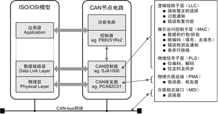
The CAN bus standards only specify the physical layer and the data link layer, requiring users to define the application layer. Different CAN standards only differ in the physical layer.
The CAN transceiver is responsible for converting between logical levels and physical signals.
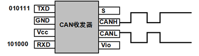
It converts logical signals into physical signals (differential levels) or converts physical signals into logical levels.
There are two CAN standards, namely ISO 11898 and ISO 11519, which have different differential voltage characteristics.
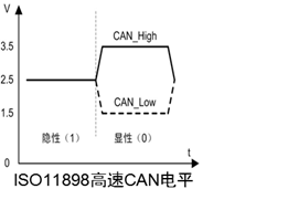
Low amplitude for high and low levels corresponds to fast transmission speeds;
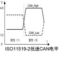
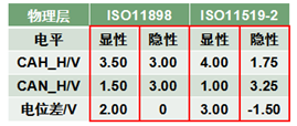
*Twisted pairs eliminate common-mode interference because the levels change simultaneously while the voltage difference remains unchanged.
Physical Layer
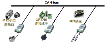
There are three types of interface devices for CAN.
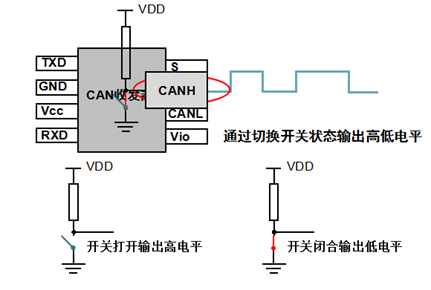
Multiple nodes are connected; as long as one is low, the bus is low; only when all nodes output high is it high. This is called “wired AND”.
The CAN bus inserts a contrary bit after five consecutive identical bits to create a transition edge for synchronization, thus eliminating accumulated errors.
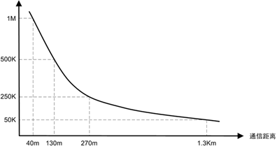
Like RS-485 and RS-232, the transmission speed of CAN is inversely proportional to the distance.
CAN bus, termination resistor connection:
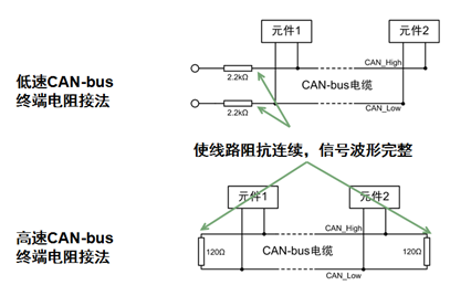
Why 120Ω? Because the characteristic impedance of the cable is 120Ω, to simulate an infinitely long transmission line.
Data Link Layer
The CAN bus transmits CAN frames, which are divided into five types: data frame, remote frame, error frame, overload frame, and inter-frame.
The data frame is used for data transmission between nodes and is the most commonly used frame type; the remote frame is used for receiving data from the sending node to the receiving node; the error frame is used to notify other nodes of frame errors when a node detects an error; the overload frame is used by the receiving node to inform the sending node of its receiving capacity; and the inter-frame is used to isolate data frames and remote frames from previous frames.
The data frame is divided into standard frame (2.0A) and extended frame (2.0B) based on the length of the arbitration segment.
Frame Start
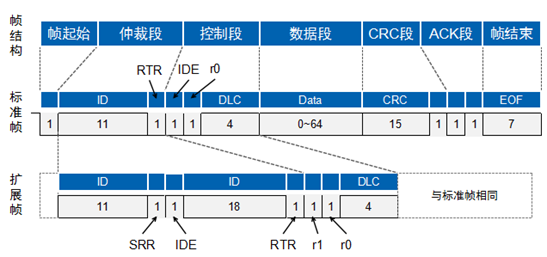
The frame start consists of one dominant bit (low level); the sending node sends the frame start, and other nodes synchronize to the frame start;
The frame end consists of seven recessive bits (high level).
Arbitration Segment
How does the CAN bus solve the problem of multi-point contention?
The arbitration segment provides the answer.
The CAN bus controller monitors the bus level while sending data; if the levels differ, it stops sending and takes other actions. If the bit is in the arbitration segment, it exits the bus contention; if it is in other segments, it generates an error event.
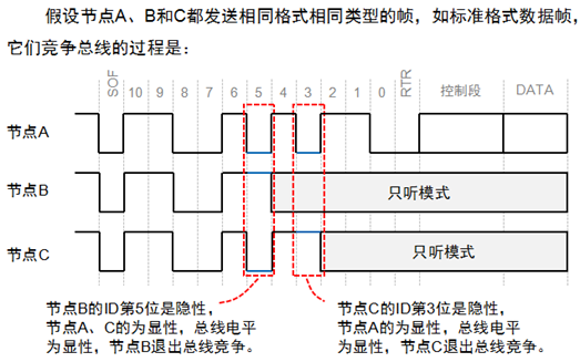
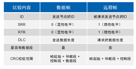
The smaller the frame ID, the higher the priority. Since the RTR bit of the data frame is a dominant level, and the remote frame is a recessive level, under the same frame format and frame ID, the data frame has a higher priority than the remote frame; since the IDE bit of the standard frame is a dominant level, and that of the extended frame is a recessive level, for the first 11 bits with the same ID, the standard frame has higher priority than the extended frame.
Control Segment
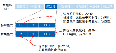
Consisting of 6 bits, the control segment of the standard frame includes the extended frame flag IDE, reserved bit r0, and data length code DLC; the extended frame control segment includes IDE, r1, r0, and DLC.
Data Segment
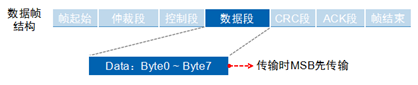
0-8 bytes, short frame structure, good real-time performance, suitable for automotive and industrial control fields;
CRC Segment
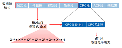
The CRC check segment consists of a 15-bit CRC value and a CRC delimiter.
ACK Segment
When the receiving node receives a frame start to the CRC segment without errors, it will send a dominant level in the ACK segment, while the sending node sends a recessive level, resulting in a dominant level.
Remote Frame
The remote frame is divided into 6 segments, and also divided into standard frame and extended frame, with the RTR bit being 1 (recessive level).
CAN is a highly reliable bus, but it also has five types of errors.
CRC Error: Occurs when the CRC values sent and received differ;
Format Error: Occurs when the frame format is invalid;
Acknowledgment Error: Occurs when the sending node does not receive acknowledgment during the ACK phase;
Bit Transmission Error: Occurs when the sending node finds that the bus level does not match the sending level during transmission;
Bit Stuffing Error: Occurs when the communication cable violates communication rules.
When any of these five errors occur, the sending or receiving node will send an error frame.
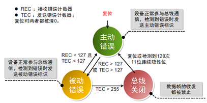
To prevent certain nodes from continuously sending error frames and interfering with other nodes’ communication, the CAN protocol specifies three states and behaviors for nodes.
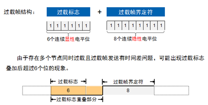
Overload Frame
When a node is not “ready” to receive, it will send an overload frame to notify the sending node.
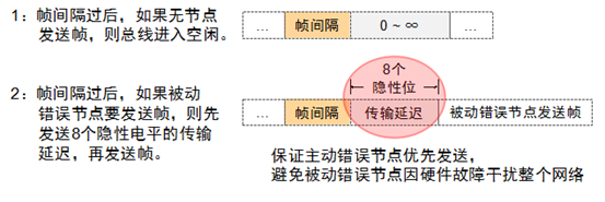
Inter-Frame
Used to isolate data frames, remote frames, and their preceding frames; error frames and overload frames do not have an inter-frame.
Building a CAN Node
Building nodes to achieve corresponding controls, divided into four parts from bottom to top: CAN node circuit, CAN controller driver, CAN application layer protocol, and CAN node application program.
Although different nodes perform different functions, they all have the same hardware and software structure.
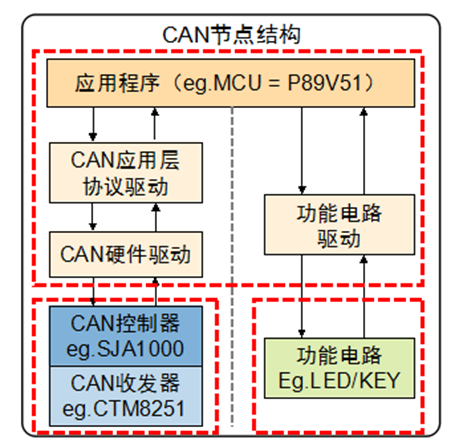
The CAN transceiver and controller correspond to the physical layer and data link layer of CAN, completing the sending and receiving of CAN messages; the functional circuit completes specific functions, such as signal acquisition or controlling peripherals; the main controller and application software parse messages according to CAN message formats to achieve corresponding controls.
The CAN hardware driver is a program running on the main controller (like P89V51) that mainly performs the following tasks: register-based operations, initializing the CAN controller, sending CAN messages, and receiving CAN messages;
If the CAN hardware driver is used directly, when changing controllers, the upper application program needs to be modified, resulting in poor portability. By adding a virtual driver layer between the application layer and hardware driver layer, the differences between different CAN controllers can be masked.
A CAN node not only completes the communication function but also includes some specific hardware functional circuits, where the functional circuit drives the functional circuit directly downwards and provides a function interface for the control function circuit upwards. Specific functions include signal acquisition, human-machine display, etc.
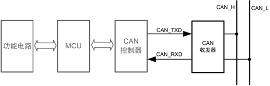
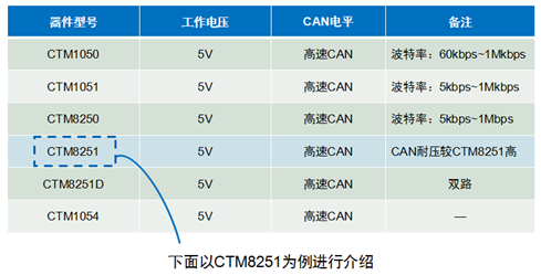
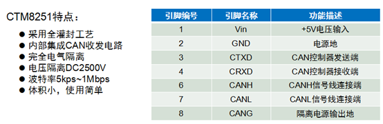
The CAN transceiver is responsible for converting the logical level of the CAN controller to the differential level on the CAN bus. There are two schemes to implement the CAN transceiver: one is to use a CAN transceiver IC (which requires power isolation and electrical isolation), and the other is to use a CAN isolation transceiver module. The latter is recommended.
The CAN controller is the core component of CAN, implementing all functions of the data link layer in the CAN protocol, capable of automatically completing the parsing of the CAN protocol. There are generally two types of CAN controllers: one is the controller IC (SJA1000), and the other is the MCU with an integrated CAN controller (LPC11C00).
The MCU is responsible for controlling the functional circuit and CAN controller: initializing CAN controller parameters when the node starts; reading and sending CAN frames through the CAN controller; handling CAN controller interrupt exceptions when they occur; outputting control signals based on received data;
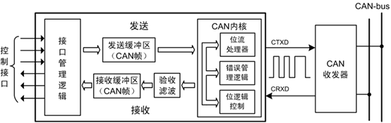
Interface management logic: interprets MCU instructions, addresses the register units of various functional modules in the CAN controller, and provides the main controller with interrupt and status information.
The send buffer and receive buffer can store complete information from the CAN bus network.
Acceptance filtering compares the stored verification code with the CAN message identifier; only the CAN frames that match the verification code will be stored in the receive buffer.
The CAN kernel implements all protocols of the data link.
Overview of CAN Protocol Application Layer
The CAN bus only provides reliable transmission services, so when a node receives a message, it must use the application layer protocol to determine who sent the data and what the data represents. Common CAN application layer protocols include: CANOpen, DeviceNet, J1939, iCAN, etc.
The CAN application layer protocol driver is a program running on the main controller (like P89V51) that defines CAN messages according to the application layer protocol, completing the parsing and assembly of CAN messages. For example, we use the frame ID to represent the node address; when the received frame ID does not match its own node ID, it is discarded directly; otherwise, it is handed over for upper-layer processing; when sending, the frame ID is set to the address of the receiving node.
CAN Transceiver
The output mode of SJA1000 has many options, with the most commonly used being the normal output mode. The input mode usually does not select the comparator mode, which can increase communication distance and reduce current in sleep mode.
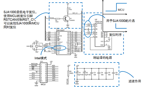
Transceivers are divided into high-speed CAN transceivers and fault-tolerant CAN transceivers based on communication speed.
The same CAN transceiver must be used in the same network.
There will be many interference signals on the CAN connection line, requiring hardware filters and anti-interference circuits to be added.
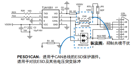
CAN isolation transceivers can also be used (which integrate filters and anti-interference circuits).
Connection Method of CAN Controller and MCU
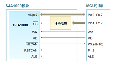
SJA1000 can be regarded as external RAM, with an address width of 8 bits, supporting a maximum of 256 registers.
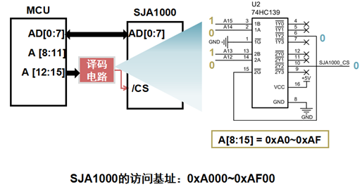
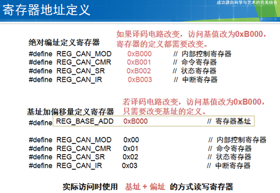
#define REG_BASE_ADDR 0xA000 // Register base addressunsigned char *SJA_CS_Point = (unsigned char *) REG_BASE_ADDR ;// Write SJA1000 registervoid WriteSJAReg(unsigned char RegAddr, unsigned char Value) {*(SJA_CS_Point + RegAddr) = Value;return;}// Read SJA1000 registerunsigned char ReadSJAReg(unsigned char RegAddr) { return (*(SJA_CS_Point + RegAddr));}
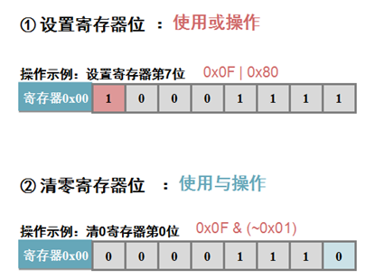
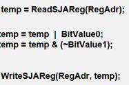
Write data from the buffer continuously into the registers
…… for (i=0;i<len;i++) { WriteSJAReg(RegAdr+i,ValueBuf[i]); }……Read multiple registers continuously into the buffer
……for (i=0;i<len;i++) { ReadSJAReg(RegAdr+i,ValueBuf[i]); }…… 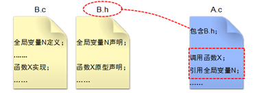 Header file inclusion scheme:
- Each program includes the header files it uses
- Each program includes a common header file that contains all other header files
#ifndef __CONFIG_H__ // Prevent header file from being included multiple times#define __CONFIG_H__#include <8051.h> // Include 80C51 register definition header file#include "SJA1000REG.h" // Include SJA1000 register definition header file// Define byte operations#define LOW_BYTE(x) (unsigned char)(x)#define HIGH_BYTE(x) (unsigned char)((unsigned int)(x) >> 8)// Define oscillator clock and processor clock frequency (users can adjust according to actual situation)#define OSCCLK 11059200UL// Macro definition of MCU clock frequency#define CPUCLK (OSCCLK / 12)#endif // __CONFIG_H__SJA1000 is in reset state after power-up and must be initialized before it can work. (1) Set Bit0 of the mode register to enter reset mode; (2) Set the clock division register to select clock frequency and CAN mode; (3) Set acceptance filtering, set verification code and mask code; (4) Set bus timer registers 0 and 1 to set the CAN baud rate; (5) Set output mode; (6) Clear Bit0 of the mode register to exit reset mode;
Mode Register
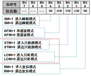 Only detection mode: SJA1000 does not check the acknowledgment bit when sending CAN frames; Listen-only mode: In this mode, SJA1000 does not send error frames, used for automatic baud rate detection; SJA1000 receives CAN frames at different baud rates. When a CAN frame is received, it indicates that the current baud rate matches the bus baud rate.
Baud Rate Settings
The CAN bus has no clock and uses asynchronous serial transmission; the baud rate is the number of data bits sent per second;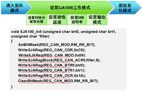
Sending CAN Frame:
Steps to send a CAN frame: 1. Check the status register, wait for the send buffer to be available; 2. Fill the message into the send buffer; 3. Start sending.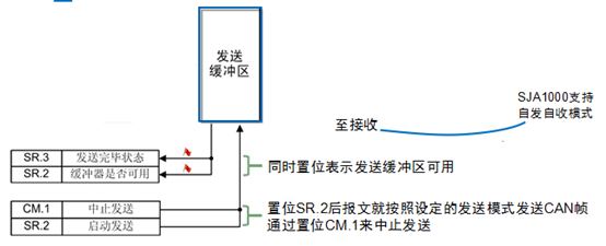 SJA1000 has a 12-byte buffer, and the message to be sent can be written through registers 16-28, or read or written through registers 96-108.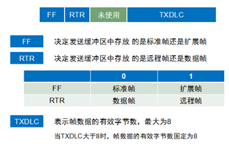
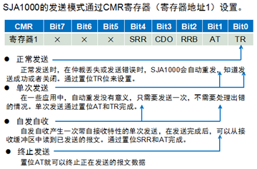
Setting Send Mode
char SetSJASendCmd(unsigned char cmd) {unsigned char ret;switch (cmd) {default:case 0: ret = SetBitMask(REG_CAN_CMR, TR_BIT); // Normal sendingbreak;case 1: ret = SetBitMask(REG_CAN_CMR, TR_BIT|AT_BIT); // Single sendingbreak;case 2: ret = SetBitMask(REG_CAN_CMR, TR_BIT|SRR_BIT);// Self-sendbreak;case 0xff: ret = SetBitMask(REG_CAN_CMR, AT_BIT);// Stop sendingbreak;}return ret;}Sending function
unsigned char SJA_CAN_Filter[8] = { // Define acceptance filter parameters, receive all frames 0x00, 0x00, 0x00, 0x00, // ACR0~ACR3 0xff, 0xff, 0xff, 0xff // AMR0~AMR3};unsigned char STD_SEND_BUFFER[11] = { // CAN sending message buffer 0x08, // Frame information, standard data frame, data length = 8 0xEA, 0x60, // Frame ID = 0x753 0x55, 0x55, 0x55, 0x55, 0xaa, 0xaa, 0xaa, 0xaa // Frame data};void main(void) // Main function, program entry{ timerInit();// Initialize D1 = 0; SJA1000_RST = 1; // Hardware reset SJA1000 timerDelay(50); // Delay 500ms SJA1000_RST = 0; SJA1000_Init(0x00, 0x14, SJA_CAN_Filter); // Initialize SJA1000, set baud rate to 1Mbps // Infinite loop, main() function should not return for(;;) { SJASendData(STD_SEND_BUFFER, 0x0); timerDelay(100); // Delay 1000ms }} Why is the frame ID 0x753? This is related to the storage format of the CAN frame in the buffer. 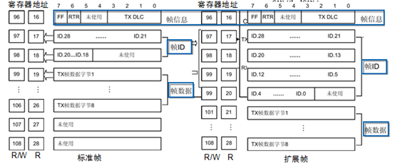
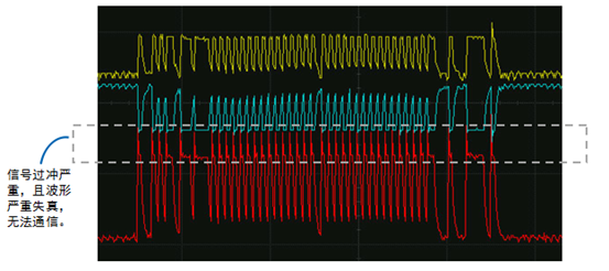
Termination resistors are very important; when the baud rate is high and no termination resistors are added, signal overshoot can be very severe. 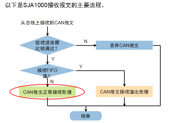 SJA1000 has a 64-byte receive buffer (FIFO), which can reduce the requirements on the MCU. The MCU can determine when the SJA1000 has received a message through polling or interrupt.
 Follow our public account, click the ” ··· ” in the top right corner of the public account homepage, set a star mark, and stay updated on the latest news in intelligent automotive electronics and software.
【Disclaimer】 The article represents the author’s independent opinion and does not represent the position of Wangcai Automotive Electronics. If there are issues related to the content, copyright, etc., please contact Wangcai Automotive Electronics for deletion or copyright negotiation within 30 days of publication.