Microcontroller ADC and DAC Applications: Analog Signal Processing Examples
Hello everyone, I am the female top laner. Today we will talk about analog signal processing in microcontrollers, focusing on the applications of ADC and DAC. These two modules can be considered important “translators” that connect microcontrollers with the real world. The ADC is responsible for converting analog signals from the real world into digital signals that the microcontroller can understand, while the DAC does the opposite, converting digital signals back into analog signals. Once you master these, you will enable the microcontroller to “understand” the sounds from sensors and also allow it to “speak” control commands.
Basics of ADC
ADC stands for Analog-to-Digital Converter.
 Its function is like a translator, converting continuously changing analog signals into discrete digital signals.
For example, imagine you are measuring room temperature. The mercury column in the thermometer changes continuously, which is an analog signal. But if you record the temperature every 5 minutes and round it to the nearest integer, this is equivalent to converting the analog signal into a digital signal.
Key parameters of ADC:
- Resolution: Usually expressed in bits, such as 8-bit, 12-bit, etc. Higher bit depth allows for a larger range of values.
- Sampling Rate: The number of samples taken per second, determining the ability to capture signal changes.
- Conversion Time: The time required to complete one conversion.
Note: High resolution does not necessarily mean high accuracy! Accuracy is also affected by factors such as reference voltage and noise.
Basics of DAC
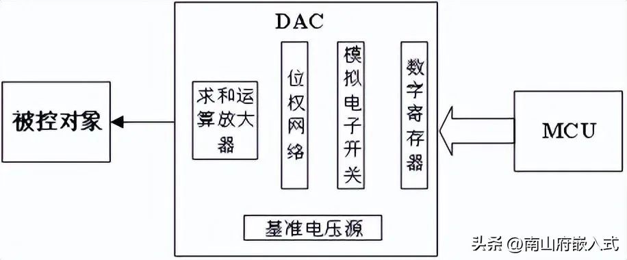
DAC stands for Digital-to-Analog Converter. Its working principle is the opposite of ADC, converting digital signals into analog signals.
Imagine you are playing an electronic piano. When you press a key, the internal DAC of the piano converts the corresponding digital note information into a continuously changing analog electrical signal, which is then played through the speaker.
The key parameters of DAC are similar to those of ADC, including resolution, conversion speed, etc.
Note: The analog signal output by the DAC usually needs to be filtered and amplified before use.
STM32 ADC Example
Taking the STM32F4 series as an example, let’s see how to use the ADC to read analog voltage.
Hardware connection:
- PA0 connected to the middle pin of the potentiometer
- Both ends of the potentiometer connected to 3.3V and GND
Code example:
#include "stm32f4xx_hal.h"

ADC_HandleTypeDef hadc1;

void ADC_Init(void)
{
    ADC_ChannelConfTypeDef sConfig = {0};

    // ADC1 initialization
    hadc1.Instance = ADC1;
    hadc1.Init.Resolution = ADC_RESOLUTION_12B;
    hadc1.Init.ScanConvMode = DISABLE;
    hadc1.Init.ContinuousConvMode = ENABLE;
    hadc1.Init.DiscontinuousConvMode = DISABLE;
    hadc1.Init.ExternalTrigConvEdge = ADC_EXTERNALTRIGCONVEDGE_NONE;
    hadc1.Init.DataAlign = ADC_DATAALIGN_RIGHT;
    hadc1.Init.NbrOfConversion = 1;
    HAL_ADC_Init(&hadc1);

    // Configure ADC channel
    sConfig.Channel = ADC_CHANNEL_0;  // PA0
    sConfig.Rank = 1;
    sConfig.SamplingTime = ADC_SAMPLETIME_3CYCLES;
    HAL_ADC_ConfigChannel(&hadc1, &sConfig);
}

uint16_t ADC_ReadValue(void)
{
    HAL_ADC_Start(&hadc1);
    HAL_ADC_PollForConversion(&hadc1, 100);
    return HAL_ADC_GetValue(&hadc1);
}
Main Steps:
- Initialize the ADC, set the resolution, conversion mode, etc.
- Configure the ADC channel, specifying the sampling time.
- Start the ADC, wait for conversion to complete, and read the result.
Practical Application: This code can be used to read the value of a photoresistor, thus implementing a simple automatic dimming table lamp. It adjusts the LED brightness based on the intensity of ambient light.
STM32 DAC Example
Next, let’s see how to use the DAC to output analog voltage.
Hardware connection:
- PA4 (DAC_OUT1) connected to an oscilloscope or voltmeter
Code example:
#include "stm32f4xx_hal.h"

DAC_HandleTypeDef hdac;

void DAC_Init(void)
{
    DAC_ChannelConfTypeDef sConfig = {0};

    // DAC initialization
    hdac.Instance = DAC;
    HAL_DAC_Init(&hdac);

    // Configure DAC channel
    sConfig.DAC_Trigger = DAC_TRIGGER_NONE;
    sConfig.DAC_OutputBuffer = DAC_OUTPUTBUFFER_ENABLE;
    HAL_DAC_ConfigChannel(&hdac, &sConfig, DAC_CHANNEL_1);
}

void DAC_SetValue(uint16_t value)
{
    HAL_DAC_SetValue(&hdac, DAC_CHANNEL_1, DAC_ALIGN_12B_R, value);
    HAL_DAC_Start(&hdac, DAC_CHANNEL_1);
}
Main Steps:
- Initialize the DAC, configure the trigger mode and output buffer.
- Set the DAC output value and start the DAC.
Practical Application: This code can be used to create a simple function signal generator. By continuously changing the DAC output value in the main loop, various waveforms such as sine waves and triangular waves can be generated.
Common Problems and Solutions
-
Unstable ADC Readings
- Reason: May be caused by external interference or power ripple.
- Solution: Increase decoupling capacitors and use the method of multiple sampling to take the average value.
DAC Output has Obvious Steps
- Reason: Insufficient DAC resolution or too low update rate.
- Solution: Use a DAC with a higher bit depth or add output filtering circuits.
ADC/DAC Accuracy Deviation is Large
- Reason: Inaccurate reference voltage or improper circuit layout.
- Solution: Use a high-precision reference voltage source, optimize PCB layout, and reduce interference from digital signals on analog signals.
Practical Suggestions
-
Use an oscilloscope to observe ADC sampling and DAC output waveforms, which helps to understand the signal change process.
-
Try to implement a simple digital voltmeter or adjustable DC power supply, which can be a good practice for ADC and DAC applications.
-
Study the DMA transfer mode of ADC, which can greatly improve sampling efficiency and is suitable for processing high-speed changing signals.
-
Explore the waveform generation capabilities of DAC, such as generating various audio signals or simulating sensor outputs.
-
Combine ADC and DAC with timer interrupts to achieve precise signal sampling and generation.
Remember, analog signal processing is a technology that requires both theoretical knowledge and practical experience. The more you practice and think, the more you will find that the applications of ADC and DAC are everywhere, from simple sensor readings to complex signal processing systems, they are all indispensable.