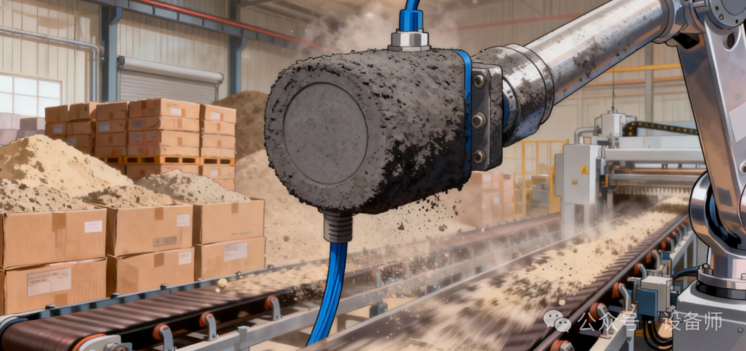
In environments with high dust concentrations, such as cement, mining, and metal processing, sensors act as “environmental sentinels”—accurately capturing data on temperature, humidity, dust concentration, and gas composition. However, we all know that these “sentinels” can easily “go on strike” after prolonged exposure to dust: either the data becomes wildly inaccurate, or they report faults directly, which can lead to false shutdowns, resulting in significant losses.
In fact, sensor malfunctions in dusty environments are not due to “bad luck,” but rather a lack of understanding of how dust damages sensors. Today, we will break down the core issues and provide a practical 4-step solution for “cleaning maintenance + protective upgrades”—all verified by frontline experience, which can save you three years of trial and error.
1. Understand First: How Does Dust Damage Sensors?
Before discussing the solutions, we need to understand the “damage pathways” of dust; otherwise, maintenance and upgrades will be futile. The common causes of sensor malfunctions can generally be categorized into four points:

1. Dust Accumulation and Blockage: The “Breathing Channel” of the Sensor is Blocked
Whether it is a diffusion-type gas sensor or an optical dust sensor, they all have a “data collection port”—for example, the permeable membrane of a gas sensor or the emission/receiving lens of an optical sensor. Dust particles (especially fine dust below PM2.5) can infiltrate through these gaps and accumulate over time: if the permeable membrane is blocked, the gas cannot enter, and the data will drop to zero; if the lens is covered with dust, the optical signal will attenuate, resulting in either a low concentration reading or triggering a “light path fault” alarm.
2. Physical Wear + Chemical Corrosion: The “Core Components” of the Sensor are Damaged
In high dust concentration environments, dust particles act like “sandpaper,” continuously rubbing against the sensor’s probe, sealing ring, and other components. For instance, certain metal probes, when subjected to hard dust over time, will have their surface coatings worn away, leading to oxidation and rust, which directly affects detection accuracy; if the dust contains acidic or alkaline components (such as corrosive dust in the chemical industry), it can corrode the circuit board, causing data drift or even burning the board.
3. Mismatched Protection Level: The “Defensive Gear” Cannot Keep Up with Environmental Intensity
Many people only consider the detection range when selecting sensors, neglecting the protection level. For example, in a mining crushing workshop, dust concentrations can exceed 2000mg/m³, accompanied by splashing debris. If an IP65-rated sensor (which only protects against low-pressure water spray) is used, dust can infiltrate through the gaps; not to mention that some sensors have unsealed cable interfaces, allowing dust mixed with moisture to enter, leading to short circuits.
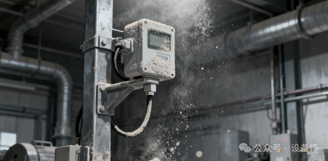
4. Chaotic Maintenance Cycles: Small Issues Turn into “Major Failures”
The most common pitfall is “repairing only when broken”—neglecting regular cleaning and only taking action when the sensor alarms, by which time dust may have already solidified on core components (for example, dust on the lens of an optical sensor may solidify due to moisture), and forced cleaning may scratch the components; even worse, calibration and maintenance records may be chaotic, making it impossible to know which sensor needs maintenance and which needs replacement.
2. Practical Solution: Cleaning Maintenance + Protective Upgrades in 4 Steps to Address Malfunctions at the Source
To address the above issues, we do not need complex technical modifications; by implementing “standardized cleaning, protective upgrades, monitoring and early warning, and closed-loop management” across four dimensions, we can reduce the sensor failure rate by over 80%.
Step 1: Standardize Cleaning Maintenance, with Precise Dust Removal for “Routine + Deep” Cleaning
Cleaning is not as simple as “blowing with compressed air”; it must follow a process based on the sensor type and dust characteristics, with the core principle being “no damage to components, no dead corners left.”
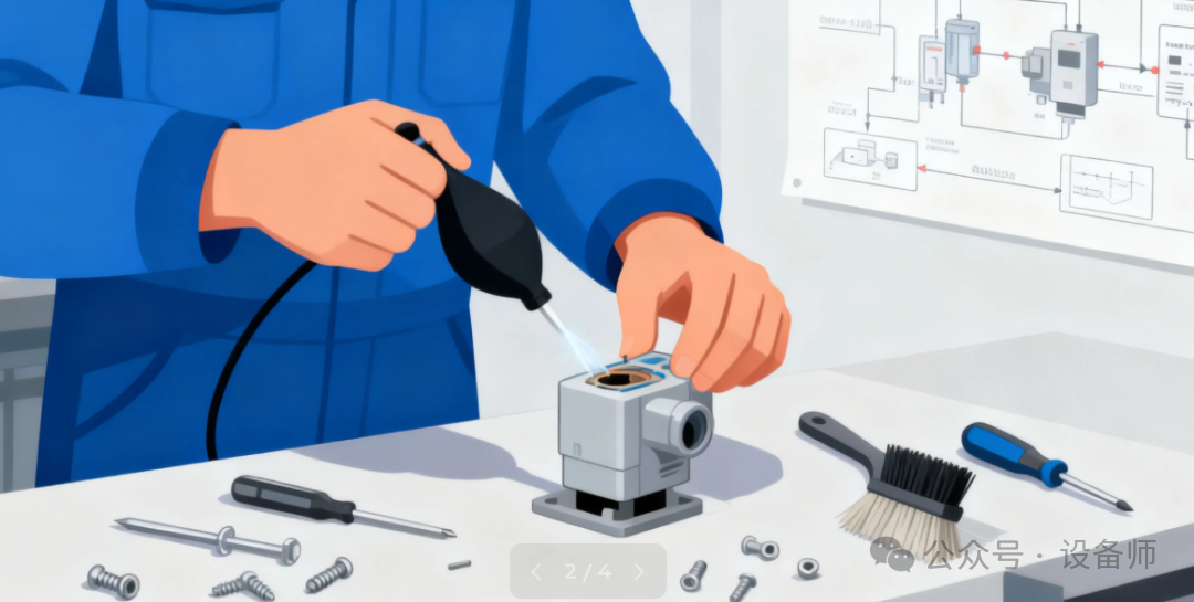
Routine Cleaning (Frequency: High dust concentration cleaned every shift, medium-low concentration cleaned daily): Focus on cleaning the “surface + collection port” using “soft brushes + low-pressure compressed air”. For example, for optical dust sensors, first use a soft brush (preferably an anti-static brush) to gently sweep the housing and lens surface, then use compressed air at 0.3-0.5MPa (with an extended nozzle) to blow at an angle towards the collection port (avoiding direct blowing that could push dust into the sensor body); for gas sensors, focus on cleaning the permeable membrane with a dry soft cloth, avoiding direct wiping with water or alcohol.
Deep Cleaning (Frequency: Once a month, adjusted based on failure frequency): Requires disassembling the housing (ensure power is off and note the wiring order), focusing on cleaning the “internal optical path + probe”. For example, for MEMS-type sensors, use a cotton swab dipped in anhydrous alcohol to gently wipe the probe surface (alcohol concentration ≥99.5%, avoiding residue); for optical sensors, use specialized optical lens paper dipped in alcohol to wipe the emission/receiving optical path, allowing it to sit for 5 minutes before reassembling to prevent incomplete evaporation of alcohol leading to short circuits.
Note: After cleaning, a “zero-point calibration” must be performed—such as placing the dust sensor in a clean air environment (like an outdoor windless area) for 30 minutes before calibrating the zero point through the controller; otherwise, the data may drift.
Step 2: Upgrade Protection Level, “Select the Right Level + Reinforce Sealing”
Protection upgrades are not about blindly replacing sensors with higher ratings, but rather “matching the environment + reinforcing locally” for the best cost-effectiveness.
1. Select the Right Basic Protection Level: Choose the IP rating based on dust concentration and working conditions, referring to this standard: for ordinary workshops (dust concentration <100mg/m³), choose IP66; for high dust concentration (100-1000mg/m³) + some moisture, choose IP67; for extreme scenarios ( >1000mg/m³ + splashing debris), choose IP68 (note that IP68 is for short-term immersion protection, confirm the sensor’s waterproof duration). Additionally, choose sensors with “dust covers” made of stainless steel (to avoid plastic aging and damage), with a hole diameter of 5-10mm (to ensure collection accuracy is not affected).
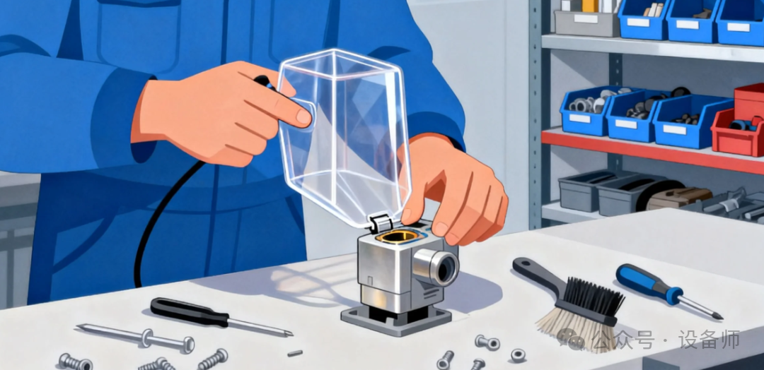
2. Reinforce Sealing at Key Locations: For existing sensors that lack sufficient protection, there is no need to replace them entirely; focus on reinforcing the sealing at “three locations”: ① Seams of the housing: apply silicone sealant (high-temperature resistant type, -40℃-200℃) along the seams in a circle, with a thickness of 1-2mm; ② Cable interfaces: use explosion-proof cable glands (especially in chemical scenarios), wrap waterproof tape around the interface after wiring, and then cover with heat shrink tubing; ③ Collection ports: install “dust filter cotton” outside the permeable membrane or lens (to be replaced regularly, such as once a week), using a polyester material with good breathability to avoid affecting detection response speed.
Step 3: Install Operational Monitoring to Provide Early Warnings for “Abnormal Signs”
There are actually “signs” before sensor malfunctions—such as increased data fluctuations and slower response times, which cannot be monitored manually; thus, a “monitoring and early warning mechanism” must be added.
1. Data Trend Monitoring: Set “fluctuation thresholds” in the PLC or monitoring system; for example, the normal fluctuation range for dust sensors is ±5%. If fluctuations exceed ±10% for three consecutive detections, the system will automatically pop up a warning (indicating “needs cleaning”); for response time, under normal conditions, the sensor’s response time should be <10 seconds; if it exceeds 30 seconds, trigger a “light path blockage” warning.
2. Status Feedback Linkage: Choose sensors with “fault output” functions; for example, when a sensor experiences “zero drift exceeding limits” or “light path faults,” not only will the system alarm, but it will also link to on-site sound and light alarms, while sending a text message to the equipment manager (via a text module) to avoid missing the opportunity to address the issue.
Tip: If the old system cannot add monitoring, create a “sensor ledger” to record each sensor’s “cleaning time, calibration data, fault records,” and use Excel to create simple trend charts; for example, if a certain sensor’s fault interval is getting shorter after cleaning, it indicates that the core component needs replacement.
Step 4: Establish Closed-Loop Management to Make “Maintenance” a Traceable System
Many solutions fail to implement well due to a lack of institutional guarantees; thus, “cleaning, calibration, and replacement” must be incorporated into daily management to form a closed loop.
1. Assign Responsibility: Attach a “label” to each sensor, clearly stating the “responsible person, maintenance cycle, calibration time”; for example, workshop operators are responsible for routine cleaning, while equipment engineers are responsible for deep cleaning and calibration, verifying records weekly.
2. Standardize Calibration: In addition to calibrating after cleaning, establish a “regular calibration cycle”—dust sensors should be calibrated once every three months (using a standard dust source), and gas sensors should be calibrated once every six months (using standard gas); calibration records must include a “calibration report,” and any non-compliant sensors should be immediately taken out of service and labeled “to be repaired.”
3. Fault Review Mechanism: Each time a sensor malfunctions, a “fault analysis form” must be filled out, detailing the “working conditions, malfunction phenomena, causes, and handling methods”; for example, if a malfunction was due to “the dust cover hole being too small, leading to insufficient collection,” standardize the dust cover hole diameter to 8mm to avoid recurrence.
3. Case Study: A Building Materials Factory Reduced Failure Rate by 82% Using the 4-Step Solution

Let me share a real case: in a cement clinker workshop, the dust concentration is consistently between 800-1200mg/m³, and previously, sensors malfunctioned 15-20 times a month, leading to false shutdowns that cost nearly 10,000 yuan per shift. After implementing our solution:
1. Routine cleaning was changed to “cleaning at every shift handover,” using anti-static brushes and low-pressure air; 2. The original IP65 sensors were replaced with IP67, sealing the seams with sealant and adding filter cotton to the collection port; 3. A fluctuation warning was added in the PLC (threshold ±10%); 4. Equipment engineers verified calibration records weekly.
One month after implementation, the monthly sensor failure count dropped to below 3, and false shutdowns were virtually eliminated, saving nearly 200,000 yuan in losses each month.
4. Final Summary: The Core Logic of Maintaining Dust Environment Sensors
We all know that “prevention is always cheaper than repair.” Maintaining sensors in dusty environments is not about “complicated technology,” but rather about “standardizing simple tasks”—cleaning must be precise in terms of “frequency + tools,” protection must match “working conditions + sealing,” monitoring must be proactive for “abnormal signs,” and management must be implemented with “responsibility + records.”
By effectively executing these four steps, not only can we solve sensor malfunctions, but we can also extend the lifespan of sensors (by at least 50%), which translates to significant savings in replacement and maintenance costs each year.
If you find this useful, save it and share it with your colleagues in the workshop. Next time you encounter sensor malfunctions, follow this plan directly! If you have questions about special working conditions, leave a comment, and let’s discuss together~