
PLC Programming Algorithm (1)
In PLC programming, there are mainly three types of quantities:Digital, Analog, and Pulse. Understanding the relationship between these three will help you master PLCs proficiently.
1. Digital Quantity is also known as logic quantity, which has only two values: 0 or 1, ON or OFF. (Digital quantities have only two states 0/1, including input and output quantities, reflecting the state).
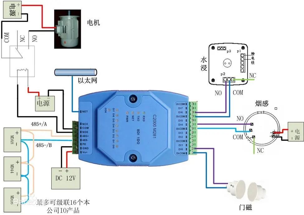
The purpose of digital quantity control is to generate corresponding digital outputs from the current input combinations and historical input sequences, allowing the system to operate in a specific sequence. Therefore, it is sometimes referred to as sequential control.
Sequential control can be divided into manual, semi-automatic, or automatic. The control principles can be decentralized, centralized, or mixed.
2. Analog Quantity refers to some continuously varying physical quantities (Digital quantities are discontinuous, reflecting the measured value of electrical quantities), such as voltage, current, pressure, speed, flow, etc.
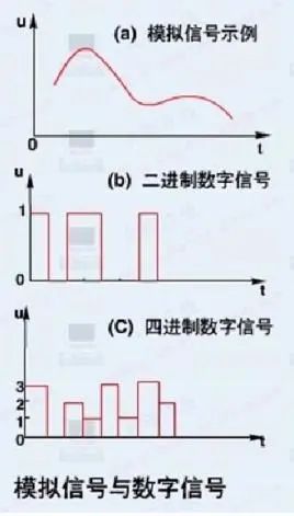
PLC has developed from relay control to microprocessor technology, making it convenient and reliable for digital control. Sinceanalog quantities can be converted into digital quantities, and digital quantities are just multi-bit digital signals, PLC can reliably handle and control the converted analog quantities.
Since continuous production processes often involve analog quantities, analog control is sometimes referred to as process control.
Most analog quantities are non-electrical, while PLC can only handle digital and electrical quantities. Therefore, to achieve conversion between them, sensors are required to convert analog quantities into digital electrical quantities.
If this electrical quantity is not standard, it must go through a transmitter to convert the non-standard electrical quantity into a standard electrical signal, such as 4-20mA, 1-5V, 0-10V, etc.
There must also be an analog input unit (A/D) to convert these standard electrical signals into digital signals, and an analog output unit (D/A) to convert the processed digital quantities back into analog quantities—standard electrical signals.
Thus, the conversion between standard electrical signals and digital quantities requires various calculations. This necessitates understanding the resolution of the analog unit and the standard electrical signals.
For example:
If the PLC analog unit’s resolution is 1/32767, corresponding to a standard electrical quantity of 0-10V, and the temperature value to be measured is 0-100℃, then 0-32767 corresponds to the temperature value of 0-100℃. Thus, the digital quantity corresponding to 1℃ is 327.67. To achieve a precision of 0.1℃, you would use 327.67/10.
Analog control includes: feedback control, feedforward control, proportional control, fuzzy control, etc. These are all calculations of the internal digital quantities of the PLC.
3. Pulse Quantity is a digital quantity that continuously alternates between 0 (low level) and 1 (high level) (a signal that instantaneously jumps from one voltage or current value to another), and the frequency is defined as the number of pulses changing per second.
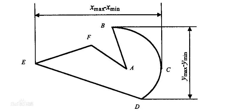
The main purpose of controlling pulse quantities is for position control, motion control, trajectory control, etc. For example, the application of pulse counts in angle control. The subdivision of a stepper motor driver is 10000 per revolution, requiring the stepper motor to rotate 90 degrees.
Thus, the required pulse count = 10000 / (360/90) = 2500
PLC Programming Algorithm (2) — Calculation of Analog Quantities
1. -10—10V. When the voltage is -10V—10V, it is converted to F448—0BB8Hex (-3000—3000) at a resolution of 6000; at a resolution of 12000, it is converted to E890—1770Hex (-6000—6000).
2. 0—10V. When the voltage is 0—10V, it is converted to 0—1770Hex (0—6000) at a resolution of 12000; at a resolution of 12000, it is converted to 0—2EE0Hex (0—12000).
3. 0—20mA. When the current is 0—20mA, it is converted to 0—1770Hex (0—6000) at a resolution of 6000; at a resolution of 12000, it is converted to 0—2EE0Hex (0—12000).
4. 4—20mA. When the current is 4—20mA, it is converted to 0—1770Hex (0—6000) at a resolution of 6000; at a resolution of 12000, it is converted to 0—2EE0Hex (0—12000).
The above is just a brief introduction; different PLCs have different resolutions, and the range of physical quantities you measure may vary. The calculation results may have some discrepancies.
Note: Requirements for wiring of analog inputs
1. Use shielded twisted pair, but do not connect the shield layer.
2. When an input is not used, short connect the V IN and COM terminals.
3. Isolate the analog signal lines from the power lines (AC power lines, high voltage lines, etc.).
4. When there is interference on the power line, install a filter between the input section and the power unit.
5. After confirming correct wiring, power up the CPU unit first, then power up the load.
6. When powering down, cut off the power to the load first, then cut off the CPU power.
PLC Programming Algorithm (3) — Calculation of Pulse Quantities
Pulse quantity control is often used for angle control, distance control, and position control of stepper motors and servo motors. Below is an example using a stepper motor to explain each control method.
1. Angle control of the stepper motor. First, clarify the subdivision number of the stepper motor, then determine the total pulse count needed for one revolution of the stepper motor.

Calculate “angle percentage = set angle / 360° (i.e., one revolution)”
“Angle action pulse count = total pulse count per revolution * angle percentage”
The formula is:
Angle action pulse count = total pulse count per revolution * (set angle / 360°)
2. Distance control of the stepper motor. First, clarify the total pulse count needed for one revolution of the stepper motor. Then determine the diameter of the stepper motor’s roller and calculate the circumference of the roller. Calculate the distance traveled per pulse. Finally, calculate the pulse count required for the set distance.
The formula is:
Set distance pulse count = set distance / [(roller diameter * 3.14) / total pulse count per revolution]
3. Position control of the stepper motor is a combination of angle control and distance control.
The above is just a simple analysis of the control methods for stepper motors, and may differ from actual practice, for reference only.
The operation of servo motors is similar to that of stepper motors, but the internal electronic gear ratio and reduction ratio of the servo motor must be considered.
Source: Power Partners

Disclaimer: All works marked "Source: XXX" in this public account are reprinted from other media, and the copyright belongs to the original author. Some images are sourced from the internet; if there is any infringement, please contact us for removal.

Related Articles
What to Do About Three-Phase Imbalance? Three Tips from Experienced Technicians
What is Step Voltage?
Four Key Points to Elaborate on Electrical Equipment Safety Organizational Measures
Why Do Analog Devices Prefer to Use 4~20mA for Signal Transmission?
 Click to read the original text for more content