Explanation of Common PCB Terminology

V-cut

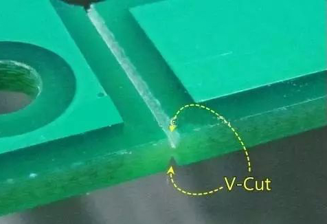
During PCB splicing, the V-shaped dividing line between two single boards and between a single board and the process edge forms a “V” shape; it is called V-cut because it is broken and separated after soldering.
Explanation of Common PCB Terminology

Purpose of V-cut

The main purpose of designing V-cut is to facilitate operators in separating the boards after circuit board assembly. When separating PCBA, a V-Cut scoring machine is usually used, which aligns the pre-cut V-shaped grooves of the PCB with the circular blade of the scoring machine. The operator then pushes it through with force; some machines are designed for automatic feeding, where pressing a button allows the blade to automatically move and cut through the V-Cut position on the circuit board. The height of the blade can be adjusted to accommodate different V-Cut thicknesses.
Reminder: In addition to using V-Cut scoring, there are other methods for PCBA separation, such as routing and postage holes.
Although the V-Cut on the PCB can also be manually broken or snapped, it is recommended not to use the manual method because the point of force can cause bending of the PCB, which easily leads to cracking of electronic components on the PCBA, especially capacitor components, thereby reducing product yield and reliability. Some issues may only gradually appear after a period of use.
Explanation of Common PCB Terminology

Design and Usage Limitations of V-Cut

Although V-Cut allows us to easily separate the boards and remove the board edges, it also has design and usage limitations.
1. V-Cut can only cut straight lines and must go all the way through, meaning V-Cut can only cut in a straight line from start to finish. It cannot turn or change direction, nor can it skip sections like a sewing line.
2. PCBs that are too thin are not suitable for V-Cut grooves. Generally, if the thickness is below 1.0mm, it is not recommended to use V-Cut because the V-Cut groove will compromise the structural strength of the PCB. When heavier components are placed on a board designed with V-Cut, gravity can cause the board to bend, which is very detrimental to SMT soldering operations (easily causing cold soldering or short circuits).
3. When the PCB passes through the reflow oven at high temperatures, it will soften and deform due to the temperature exceeding the glass transition temperature (Tg). If the V-Cut position and groove depth are not well designed, it can lead to more severe deformation of the PCB, which is detrimental to the secondary reflow process.

Definition of V-Cut Angles

Generally, V-Cut can be defined at three angles: 30°, 45°, and 60°, with 45° being the most commonly used.
The larger the angle of the V-Cut, the more material is removed from the board edge, and correspondingly, the PCB traces must be moved inward to avoid being cut by the V-Cut or damaged during cutting.
The smaller the angle of the V-Cut, theoretically, the more beneficial it is for PCB space design, but it is not advantageous for the lifespan of the V-Cut saw blades used by PCB manufacturers, as a smaller V-Cut angle means the saw blade must be thinner, making it more prone to wear and breakage.
(Content compiled from the internet)
Explanation of Common PCB Terminology

During the pandemic, learning cannot stop. Before the end of the pandemic, KuaiDian Academy will collaborate with Tencent Classroom to continue offering some courses for everyone to learn online for free!

↓↓↓

Explanation of Common PCB Terminology

Leave a Comment

