NOR Flash Storage Principles: Detailed Explanation of the Storage Mechanism of 0s and 1s
NOR Flash, as a key non-volatile memory in embedded systems, has a storage mechanism based on the physical characteristics of floating MOSFETs. This article systematically analyzes its storage unit structure, operational principles, and technical constraints.
1. Storage Unit: The Physical Basis of Floating Gate MOSFETs
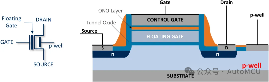
The storage unit of NOR Flash is composed of floating gate MOSFETs, with the core feature being the floating gate structure. The floating gate is completely isolated by the tunnel oxide layer and the ONO layer, forming a charge capture region. By controlling the number of electrons stored in the floating gate, non-volatile data storage can be achieved:
- Erase State: Floating gate has no charge, threshold voltage (Vth) is low (<5.5V)
- Program State: Floating gate captures electrons, threshold voltage increases (>6.5V)
The stability of the floating gate charge is ensured by the oxide barrier, with a charge leakage rate of less than 1% per year (at 25°C), ensuring long-term data reliability.
2. Three Main Operational Mechanisms of NOR Flash
NOR Flash supports three operations:Erase, Program, and Read.
2.1 Erase (0 → 1)
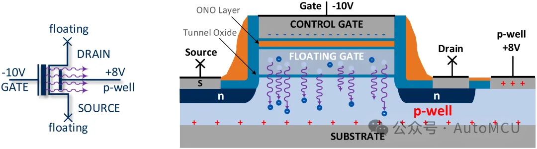
Physical Principle: Fowler-Nordheim tunneling effect
Voltage Conditions: P-well applies +8V, control gate applies -10V, source and drain are floating
Process:
-
Electric field strength reaches 20MV/cm, electrons tunnel through the tunnel oxide layer
-
Floating gate charge is depleted, threshold voltage drops to erase state (Vth < 5.5V)
Key Features:
- Erase current is minimal (nA level), requiring 50-100ms
- Operation is performed in blocks, cannot erase byte by byte
2.2 Programming (1 → 0)
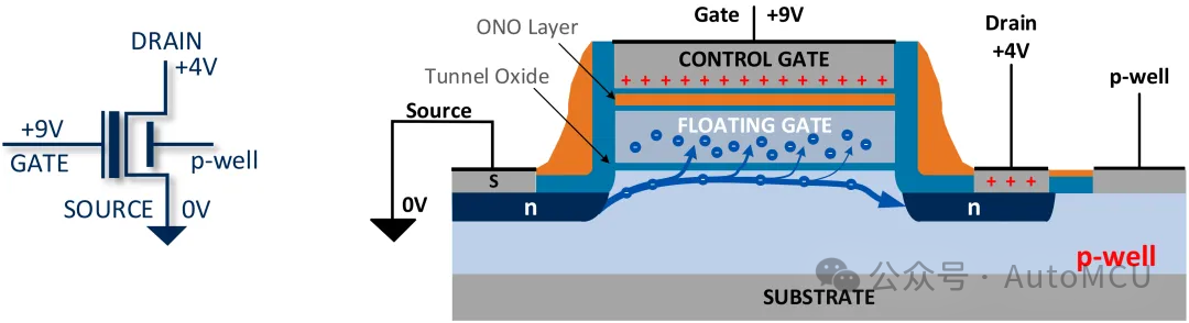
Physical Principle: Hot Carrier Injection
Voltage Conditions: Control gate +9V, source 0V, drain +4V
Process:
-
Source-drain electric field >5MV/cm, electrons gain sufficient energy to inject into the floating gate
-
Electrons are captured by the floating gate traps, forming stable charge storage
Key Features:
- Threshold voltage is positively correlated with injected electron concentration
- Effective programming requires Vth ≥ 6.5V (with a 1V safety margin)
- Programming time is 200-500μs, much faster than erase operations
2.3 Reading: State Determination Mechanism
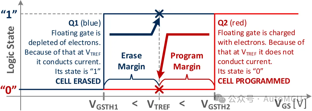
Principle: Threshold voltage comparisonReference Voltage: VTREF = 5.5VDetermination Logic:
| State | Floating Gate Charge | Vth | Conducting Current | Logical Value |
|---|---|---|---|---|
| Erase | None | <5.5V | Conducting | 1 |
| Program | Present | >6.5V | Not Conducting | 0 |
Reading Process:
- Apply 5.5V reference voltage to the control gate
- Detect source-drain current:
- Current > 10μA → logical “1” (erase state)
- Current < 1nA → logical “0” (program state)
3. Key Operational Constraints and Technical Essence
3.1 Operational Sequence Rules
NOR Flash must follow the “Erase → Program” sequence; violating this rule will lead to:
- Over-programming: Attempting to write 1 directly to an already programmed unit (0)
- Failure Symptoms:
- Threshold voltage abnormally increases (>7V)
- Triggers ECC (Error-Correcting Code) errors during reading
- Data reliability decreases (typical error rate >10⁻⁶)
Technical Essence: The programming operation relies on the hot electron injection mechanism, which can only add electrons to the floating gate (1→0). Converting 0 (high threshold) to 1 (low threshold) requires removing electrons, a process that can only be achieved through the erase operation (Fowler-Nordheim tunneling). Forcibly programming will lead to floating gate charge overload, triggering over-programming failures.
3.2 Voltage Stress Specifications
| Electrode | Maximum Safe Voltage | Function |
|---|---|---|
| P-well | +8V | Generate tunneling electric field |
| Control Gate | -10V ~ +9V | Control electron injection/release |
| Source | +4V | Provide hot electron source |
| Drain | 0V (floating) | No current path |
Questions and Thoughts
Q: How are 0s and 1s represented in the storage unit of NOR Flash?
A: The amount of charge stored in the floating gate determines the representation of 0s and 1s. When the floating gate has no charge (erase state), the threshold voltage is below the reference voltage (Vth < 5.5V), the MOSFET conducts current, representing logical “1”; when the floating gate captures electrons (program state), the threshold voltage is above the reference voltage (Vth > 6.5V), the MOSFET does not conduct current, representing logical “0”.
References
- NOR Flash Memory Erase Operation – https://www.renesas.com/en/document/apn/nor-flash-memory-erase-operation
Next Issue Preview: Core Mechanisms of NOR Flash: Failure Modes and Automotive Grade Reliability Assurance (Part Three of the Series)