Overview of SMART Panels
The SMART panels are divided into the first generation product SMART LINE and the second generation product SMART LINE IE. The first generation does not have an Ethernet port, including Smart 700 and Smart 1000; the second generation integrates an Ethernet port, including Smart 700 IE and Smart 1000 IE. Currently, the second generation SMART LINE IE series is on sale, while the first generation products have been discontinued.
Compared to the first generation SmartLine, the SmartLine IE has the following main advantages:
-
64K true color display, significantly improved compared to the first generation’s 256 colors.
-
Added industrial Ethernet interface (supports self-crossing function). This Ethernet port can connect S7-200 SMART and LOGO! 0BA7 devices, and can connect multiple controllers simultaneously (up to 3).
-
Expanded serial communication capabilities.
Number of Connections
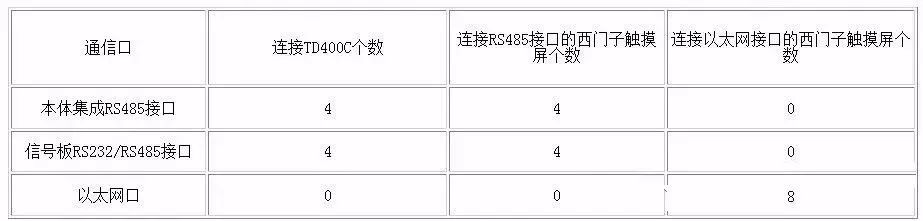
The S7-200 SMART CPU can connect to Siemens HMI devices that support PPI protocol either through the integrated RS485 port or signal board, or through the integrated Ethernet port to connect to Siemens HMI devices that support S7 protocol.
When the CPU’s three physical interfaces are connected to Siemens HMI devices simultaneously (including the signal board), the maximum number of connection resources is 16.
Table 1. CPU Connection Capabilities
Supported PLCs by Smart Panels:
First generation SmartLine (without Ethernet interface): S7-200, OMRON CP1 series, Mitsubishi FX series, Modbus RTU. Note: Only one communication connection can be established; otherwise, Smart Panels cannot start the project (white screen).
Second generation SmartLine-IE: Serial port: S7-200, OMRON CP1 series, Mitsubishi FX series, Modbus RTU, Delta (DVP-SV/ES2 series); Ethernet: S7-200 (CP243-1), Smart200, LOGO!
Smart Panels can only connect to one device via serial port and can connect to three devices via Ethernet, but serial and Ethernet cannot be used simultaneously (compilation will fail).
Note: Only one of the serial port and Ethernet port can be used; otherwise, compilation will fail.
Creating a Project
Users need to use WinCC Flexible 2008 SP2 China or later versions to configure the first generation product SmartLine. For the second generation product SmartLine IE, only WinCC Flexible 2008 SP4 China can be used for configuration.
Users can create a project directly in WinCC Flexible or use the wizard. The following mainly introduces how to create a project directly.
Double-click the SIMATIC WinCC flexible icon on the desktop to launch WinCC flexible. In the startup screen, select “Create an empty project”, as shown in Figure 1. After left-clicking “Create an empty project”, the “Device Selection” interface as shown in Figure 2 will open. In this interface, select the device used, taking Smart 1000 IE as an example.
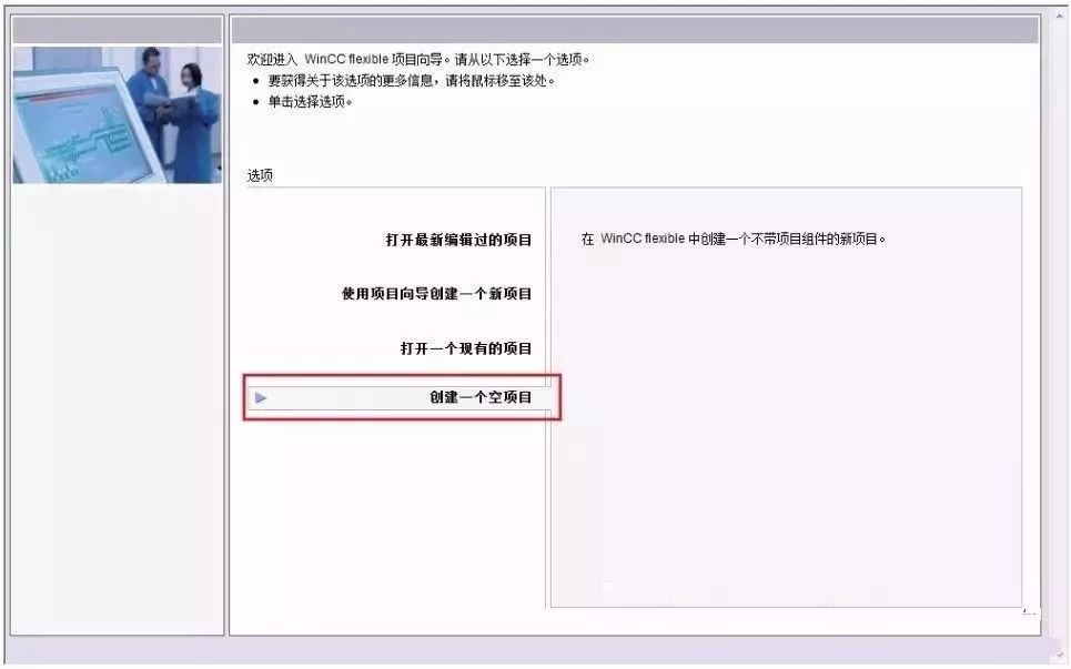
Figure 1. Directly Create Project
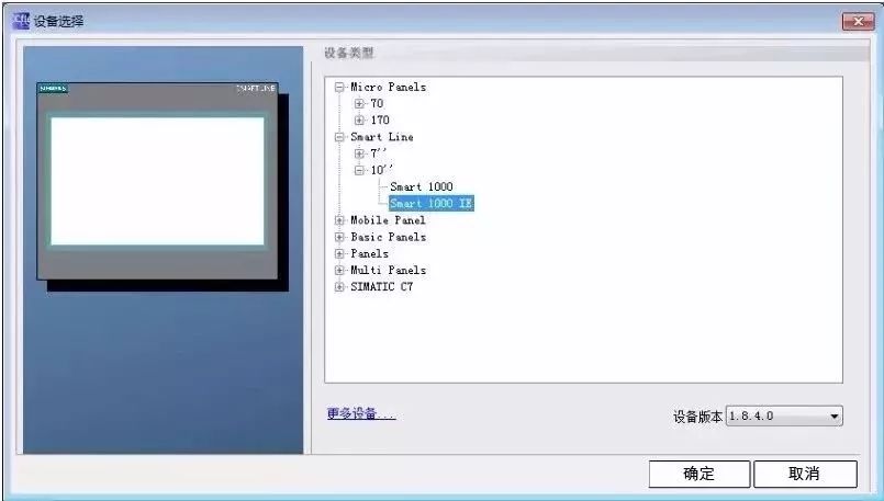
Figure 2. Device Selection
Configuring Communication Connection
Users can configure the PPI communication between Smart 1000 IE and S7-200 SMART CPU through the following steps.
Step 1: In the main working window of WinCC flexible, expand the project structure on the left side, select “Project” > “Communication” > “Connection”, and double-click the “Connection” icon to open the properties window for “Connection Settings”, as shown in Figure 3.
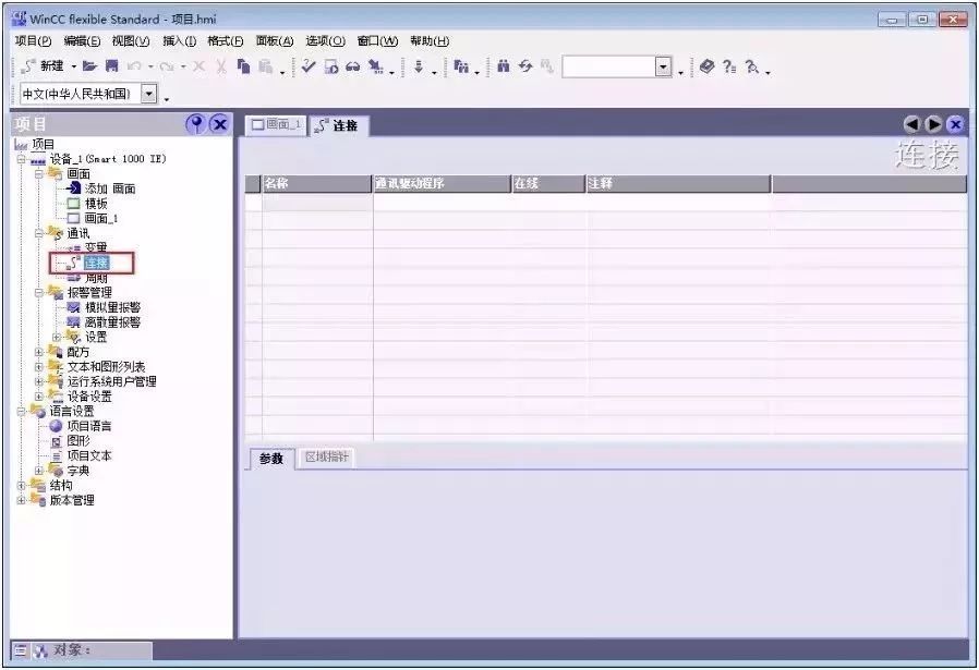
Figure 3. Open Connection Window
Step 2: In the “Connection” window, double-click the blank table below the name, or right-click and select “Add Connection” from the shortcut menu to add a connection with the CPU, as shown in Figure 4.
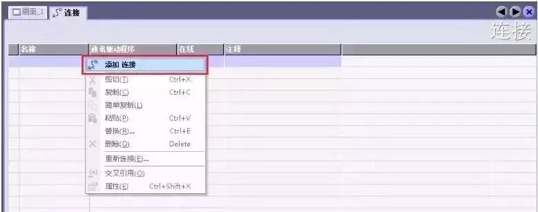
Figure 4. Add Connection
Step 3: After adding the connection, users can modify the default connection name “Connection_x” according to project needs and choose the “Communication Driver” and whether to go online. Since the connected device is S7-200 SMART CPU, select “SIAMTIC S7 200 SMART” as the communication driver from the dropdown menu under “Communication Driver”, and activate the online connection, as shown in Figure 5.
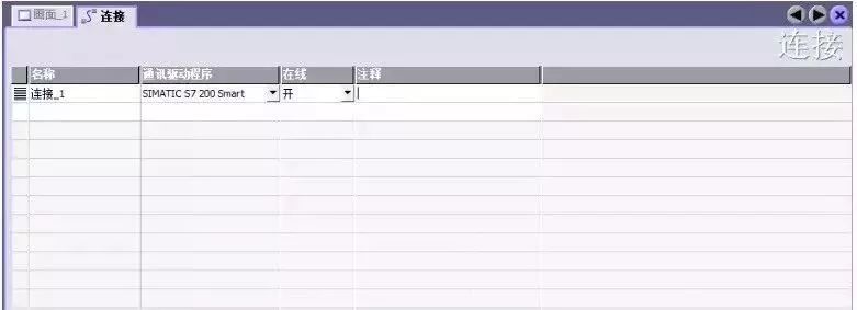
Figure 5. Configure Connection
Step 4: Set the connection parameters. First, select the interface of Smart 1000 IE as “IF1 B”, which is the RS422/485 physical interface of the touchscreen. After selecting this interface, the parameter settings window for this interface will automatically display below. Set the communication baud rate of the touchscreen to 187500, and the station address to 1.
Next, in the “Network” window, select “PPI” as the communication protocol for both parties.
Finally, in the “PLC Device” window, set the station address of the CPU; here, set the station address of the CPU to 2, as shown in Figure 6.
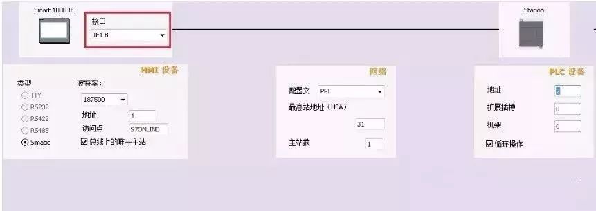
Figure 6. Connection Parameter Settings
Note: The CPU address must be different from the HMI device address; they cannot be the same.
Step 5: Set the baud rate and station address of the S7-200 SMART CPU. In the project tree of the STEP 7 Micro/WIN SMART software, select the system block and press the Enter key to open the system block window as shown in Figure 7. The station address and baud rate set for the CPU’s RS485 port must be consistent with the configuration in Figure 6; the CPU’s station address is 2, and the communication baud rate is 187.5 kbps.
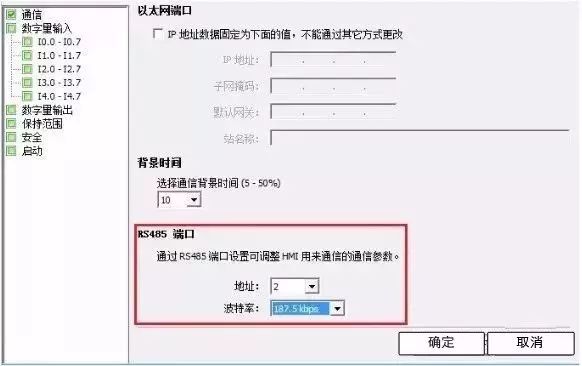
Figure 7. S7-200 SMART Communication Port Settings
Thus, the PPI communication between Smart 1000 IE and S7-200 SMART CPU has been configured.
Starting the Operation Screen
When powering on the Smart 1000 IE device, the startup screen will briefly appear, as shown in Figure 8. The meanings of the three buttons in the figure are as follows:
Transfer: HMI device is set to transfer mode.
Start: Start the project loaded on the HMI device.
Control Panel: Click this button to enter the control panel of the HMI device, where users can select transfer mode, add passwords, etc.
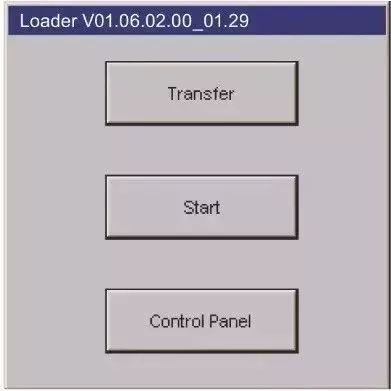
Figure 8. Startup Screen
Downloading Project Files
To download the configured project to the Smart 1000 IE device, first ensure that the communication port of the HMI device is activated, which can be set via the HMI device’s “Control Panel” > “Transfer”, as shown in Figure 9. If using serial mode to download the project, first check the “Enable Channel” next to “Serial”..
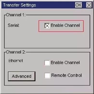
Figure 9. Enable Communication Port
Secondly, use the original Siemens PPI programming cable to download the project; both RS-232/PPI cable (Order No. 6ES7 901-3CB30-0XA0) and USB/PPI cable (Order No. 6ES7 901-3DB30-0XA0) can be used. When using the USB/PPI cable, its E-STAND version must be 05 or higher.
Then, in the WinCC flexible software menu, select “Project” > “Transfer” > “Transfer”, as shown in Figure 10. Click “Transfer” to open the “Select Device for Transfer” window, as shown in Figure 11. In the “Select Device for Transfer” window, users can choose the transfer mode as “Serial” or “Serial (via USB-PPI cable)”; select the latter for transfer.
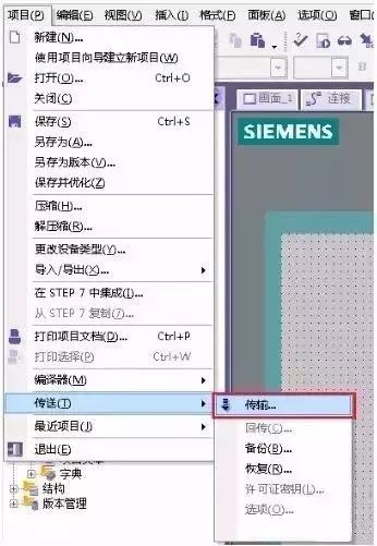
Figure 10. Open Transfer Settings
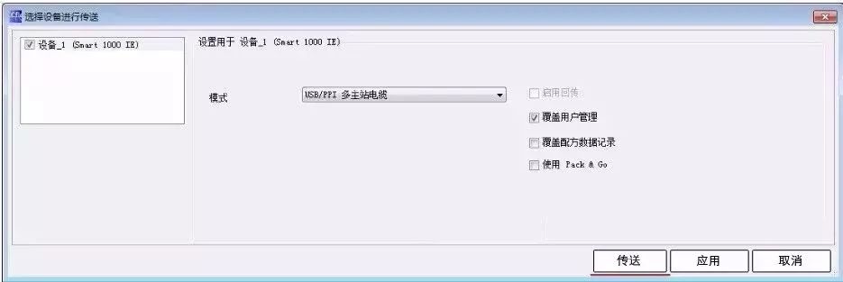
Figure 11. Transfer Settings
After powering off and then powering on the Smart 1000 IE device, the HMI device will display the startup screen. Click the Transfer button to set the HMI device to “Transfer” mode.
Then, in the WinCC flexible software, select “Project” > “Transfer” > “Transfer”, click the “Transfer” button in Figure 11, and when the transfer status in the HMI device shows “Transfer Complete”, the project has been successfully transferred to the HMI device via serial mode.
(Content sourced from the internet, copyright belongs to the original author)
Disclaimer: If there are copyright issues, please contact for deletion!
No individual or organization bears any related legal responsibility.
Recommended Reading:
Benefits Coming! Free Learning of Schneider SoMachine Detailed Course
The first batch of IAAT certificates has been issued; please check, engineers!
Important News | Electrician Certificate Revised~~
For detailed course inquiries:
Teacher Cheng 15315136942 (WeChat same number)
Join the group for technical communication:536682860 (QQ group)