1. Project Overview (Free related project link at the end)
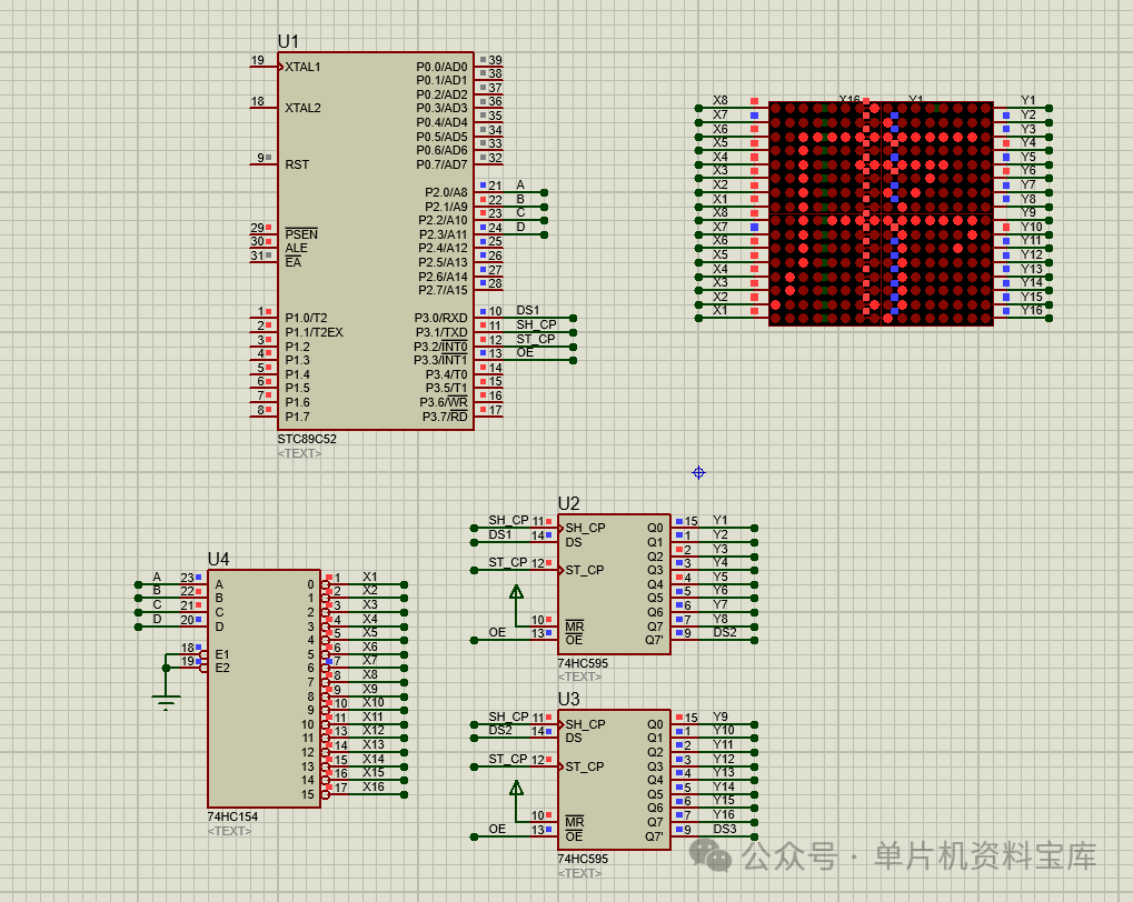
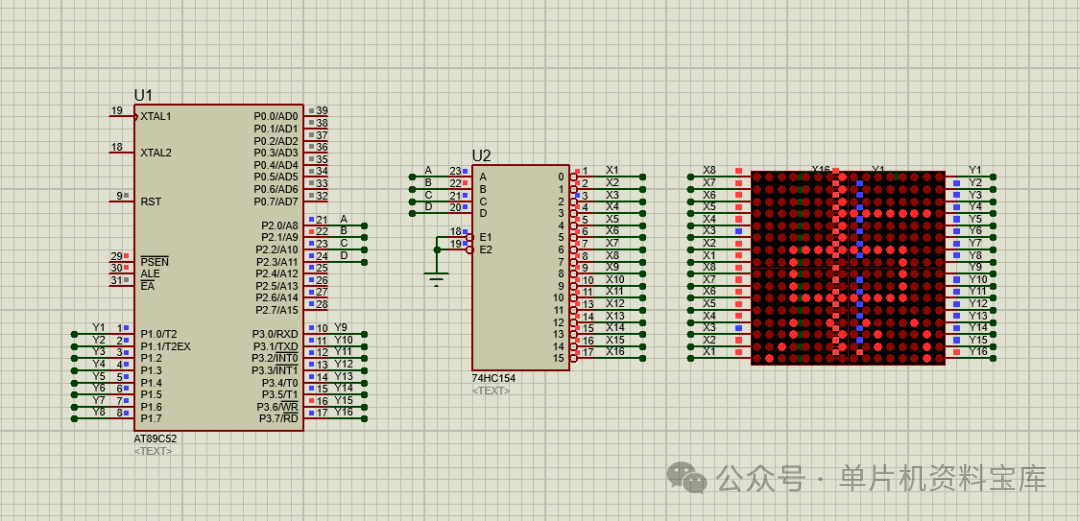
This project uses a microcontroller as the control core, combined with the 74HC595 shift register, 74HC154 decoder, and a 16*16 common cathode/common anode dot matrix display, to build a low-cost, highly stable dot matrix display system. The system supports static text, scrolling text, simple graphics, and dynamic animations, making it widely applicable in scenarios such as small information bulletin boards, electronic signage, smart device status indicators, and teaching demonstration platforms. It combines practicality with educational value, serving as a typical application case for microcontroller peripheral interface expansion and dot matrix driving technology.
2. Core Components and Function Description
1. Core Control Unit: Microcontroller
A general-purpose 8-bit microcontroller (such as STC89C52, AT89C51, etc.) is selected as the main control chip, responsible for system logic control, data processing, and driving signal output tasks. The microcontroller communicates with peripheral chips through I/O ports, receives user commands (such as switching display content via buttons), and transmits the pre-processed display data to the driving circuit to achieve precise display control of the dot matrix screen.
2. Row Driver Chip: 74HC154 4-16 Line Decoder
- Core Function: Decodes the 4-bit binary address signal output from the microcontroller into 16 independent row selection signals, achieving 16-row scanning control for the 16*16 dot matrix display.
- Advantages: The 74HC154 is a high-speed CMOS chip with a wide operating voltage range (2V-6V), and outputs low-level signals effectively, allowing direct driving of the dot matrix display’s row pins without additional amplification circuits; it only requires 4 microcontroller I/O ports to expand to 16 row control signals, significantly saving microcontroller resources and simplifying hardware wiring.
3. Column Driver Chip: 74HC595 Shift Register
- Core Function: Converts the serial display data output from the microcontroller into parallel data output, controlling the on/off state of the dot matrix display’s column pins.
- Design Logic: The 16*16 dot matrix display requires 16 column signals, using 2 cascaded 74HC595 chips (each providing 8 parallel outputs). Through the three control pins: “Serial Data Input (SDI), Shift Clock (SCK), and Latch Clock (RCK),” it achieves synchronous transmission and latching of 16 column data, occupying only 3 microcontroller I/O ports, greatly optimizing port utilization.
- Additional Value: The 74HC595 supports cascading expansion; if an upgrade to a 32*16 or 16*32 dot matrix display is needed later, only the corresponding number of 74HC595 chips need to be added without modifying the core control logic, providing good scalability.
4. Display Terminal: 16*16 LED Dot Matrix Display
A common cathode or common anode 16*16 dot matrix display is selected (this project uses common cathode as an example), consisting of 256 LED diodes arranged in 16 rows and 16 columns, with each LED corresponding to a display pixel. By coordinating the row selection signals and column data signals, independent control of individual pixel points is achieved, which can then be combined to form text, graphics, or animation effects. The dot matrix display uses a pin header interface, facilitating soldering connections with the driving circuit, and features low power consumption and fast response speed, making it suitable for long-term stable operation.
3. System Working Principle
This system adopts a dynamic scanning driving method, with the core logic being “row selection + column data synchronous latching.” The specific workflow is as follows:
- Row Selection Control: The microcontroller outputs a 4-bit address signal to the 74HC154, which decodes and selects one of the 16 rows (active low), allowing the corresponding anodes of all LEDs (common cathode matrix) in that row to conduct;
- Column Data Transmission: Simultaneously, the microcontroller transmits the 16 column display data (binary 0/1, where 0 means on and 1 means off) for the currently selected row serially to the 2 cascaded 74HC595 chips;
- Data Latching and Display: Once all 16 column data have been transmitted, the microcontroller triggers the latch clock signal of the 74HC595, latching the serial data as parallel data and outputting it to the column pins of the dot matrix display, lighting the LEDs in the selected row according to the column data state;
- Row Scanning Cycle: The microcontroller rapidly switches the row selection signals (scanning frequency ≥ 50Hz to avoid visible flicker), sequentially selecting each row and updating the corresponding column data, utilizing the human eye’s persistence of vision effect to achieve a complete display of 256 pixel points, presenting continuous and stable text or graphics.
4. Software Design Framework
The software is developed in C language, adopting a modular programming approach, with core modules including:
- Initialization Module: Configures the microcontroller I/O ports (setting row control and column control pins to output mode), and the timer (to control scanning frequency and avoid flicker);
- Data Preprocessing Module: Converts the text to be displayed (such as ASCII codes) and graphics into 16*16 dot matrix codes (generated by dot matrix pattern software and stored in the microcontroller’s Flash memory);
- Driver Control Module: Implements the row selection logic for the 74HC154, the serial-to-parallel conversion and data latching logic for the 74HC595, encapsulated as independent function calls;
- Display Function Module: Includes static display (fixed text/graphics), scrolling display (left/right/up/down scrolling text), animation display (frame sequence switching), etc., supporting mode switching via buttons;
- Interrupt Handling Module: Utilizes timer interrupts to trigger the scanning cycle, ensuring stable scanning frequency and improving display smoothness.
5. Project Advantages and Application Scenarios
1. Core Advantages
- Hardware Simplification: By combining the 74HC595 and 74HC154, only 7 microcontroller I/O ports are needed to drive the 16*16 dot matrix display, resulting in low resource usage and cost (total cost of core components ≤ 50 yuan);
- High Stability: Adopting a dynamic scanning method, the conduction time of individual LEDs is short, leading to low power consumption and effectively extending the lifespan of the dot matrix display; CMOS chips have strong anti-interference capabilities, suitable for operation in complex environments;
- Strong Scalability: Supports expansion of dot matrix display size (e.g., 16*32, 32*32), display function upgrades (e.g., adding temperature/humidity data display), and is compatible with various microcontroller models;
- Easy to Learn: Covers core technologies such as microcontroller I/O port control, serial-to-parallel conversion, decoder applications, and dynamic scanning, making it an ideal training project for students in electronic information, automation, and related fields.
2. Typical Application Scenarios
- Small Information Display: Electronic signage for shops, office notices, elevator floor indicators;
- Smart Device Support: IoT node status display, sensor data visualization (e.g., temperature and humidity values);
- Teaching Demonstration: Microcontroller peripheral interface expansion, teaching of dot matrix driving principles, introductory practice for embedded systems;
- Creative Electronic Projects: Personalized text screens, festive animation screens, small electronic billboards.
6. Project Expansion Directions
- Function Upgrade: Add Bluetooth/WiFi modules (such as HC-05, ESP8266) to enable remote control of display content via mobile apps;
- Hardware Expansion: Expand to a 32*32 dot matrix display, supporting more complex graphics, Chinese characters, or simple image displays;
- Interaction Optimization: Add a key matrix or touch module to support manual switching of display modes and brightness adjustment;
- Practical Function Addition: Combine with the DS1302 clock module to display time, and with the DHT11 sensor to display environmental temperature and humidity.
Free Link:
Link: https://pan.baidu.com/s/1jDqvjYUKqLTh40k7IDHvwg
Extraction Code: 359w