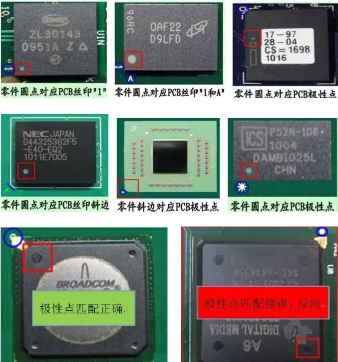
Polarity components require special attention throughout the PCBA processing, as incorrect orientation of directional components can lead to mass failures and the complete failure of the PCBA board. Therefore, it is extremely important for engineering and production personnel to understand SMT polarity components.
1. Definition of Polarity
Polarity refers to the positive and negative terminals of a component or the first pin matching the positive and negative terminals on the PCB (Printed Circuit Board) in the same direction. If the direction of the component does not match that on the PCB, it is referred to as reverse polarity failure.
2. Methods for Identifying Polarity
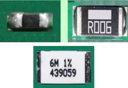
1. Chip Resistor (Resistor) – No Polarity
2. Capacitor (Capacitor)
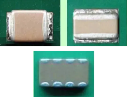
2.1 Ceramic Capacitor – No Polarity
▲ Figure 2.2.1 Ceramic Capacitor (No Polarity)
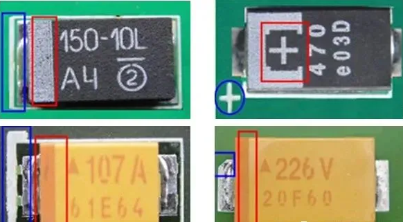
2.2 Tantalum Capacitor – Has Polarity
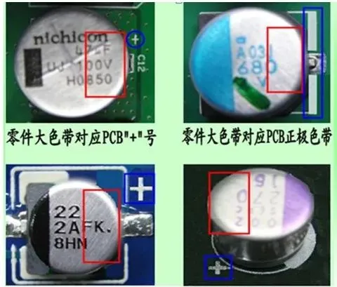
Positive terminal indicators on the PCB and components: 1) Color band indicator; 2) “+” sign indicator; 3) Slant angle indicator.▲ Figure 2.2.2 Tantalum Capacitor – Has Polarity
2.3 Aluminum Electrolytic Capacitor – Has Polarity
Component indicators: Color band represents negative; PCB indicators: Color band or “+” sign represents positive terminal.▲ Figure 2.2.3 Aluminum Electrolytic Capacitor – Has Polarity
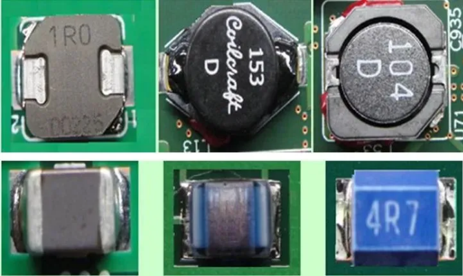
3. Inductor (Inductor)
3.1 Chip Coil
Chip inductors and similar two-terminal packages do not require polarity.▲ Figure 2.3.1 Chip Inductor – No Polarity
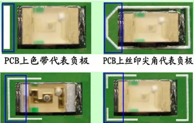
Component negative terminal indicator: Green represents negative;
PCB negative terminal indicators: 1) Vertical bar represents; 2) Color band represents; 3) Silkscreen sharp corner represents; 4) Silkscreen “匚” frame represents.
▲ Figure 2.4.1 Surface-Mount LED Device
5. Diode (Diode)
5.1 SMT Surface-Mount Diode
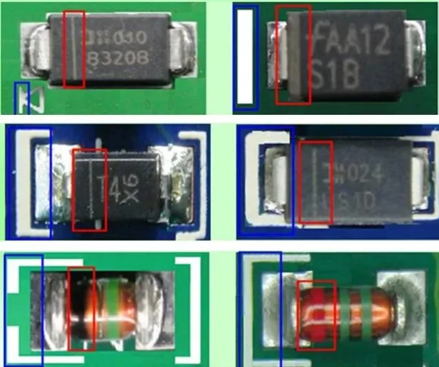
Surface-mount diodes have polarity.
Component negative terminal indicators: 1) Color band, 2) Groove, 3) Color indicator (glass body);
PCB negative terminal indicators: 1) Vertical bar indicator, 2) Color band indicator, 3) Silkscreen sharp corner indicator, 4) “匚” frame indicator.
▲ 251. Surface-Mount Diode with Polarity
6. Integrated Circuit (Integrated Circuit)
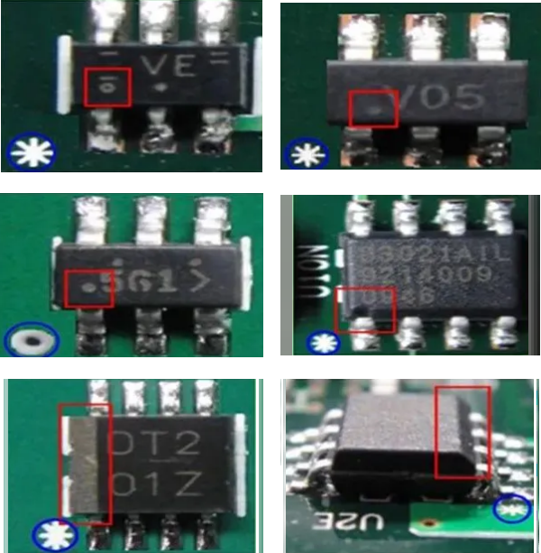
6.1 SOIC Type Package
This type of package has polarity. Polarity indicators: 1) Color band, 2) Symbol, 3) Dimple, Groove, 4) Slant edge▲ Figure 2.6.1 Polarity Marking of Integrated Circuit
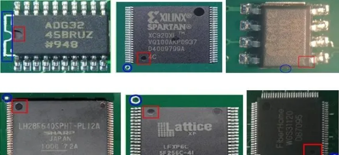
6.2 SOP or QFP Type Package
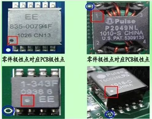
This type of package has polarity. Polarity indicators: 1) Dimple/Groove indicator, 2) One of the points differs in size/shape from the other two/three points.▲ Figure 2.6.2 SOP and QFP Package
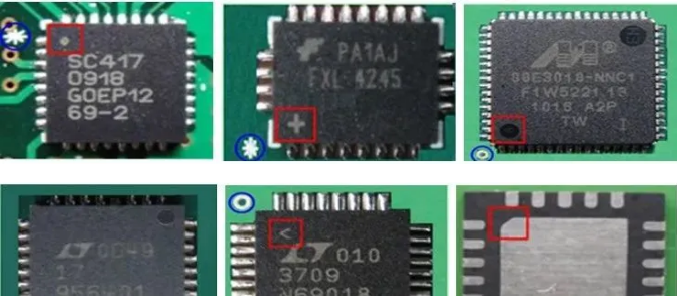
6.3 QFN Type Package
This type of package has polarity. Polarity indicators: 1) One point differs in size/shape from the other two points, 2) Slant edge indicator, 3) Symbol indicator (horizontal bar/“+” sign/dot).▲ Figure 2.6.3 QFN Package with Polarity