The function of an inverter is to convert the industrial frequency (50Hz or 60Hz) AC power supply into a frequency-variable AC power supply for the motor, providing speed control by changing the frequency of the AC power supply. There are many types of inverters, mainly divided into two categories: AC-DC-AC inverters and AC-AC inverters.
The AC-DC-AC inverter utilizes a circuit to first convert the industrial frequency power supply into a DC power supply, then converts the DC power supply into a frequency-variable AC power supply, which is then provided to the motor. By adjusting the frequency of the output power supply, the motor speed can be changed.
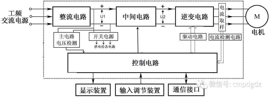
Typical structural block diagram of an AC-DC-AC inverter
The AC-AC inverter directly converts the industrial frequency power supply into a frequency-variable AC power supply and provides it to the motor, changing the motor speed by adjusting the frequency of the output power supply.
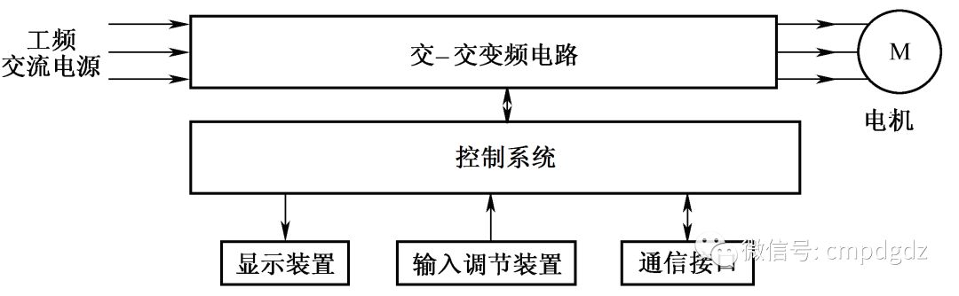
Typical structural block diagram of an AC-AC inverter
The AC-AC inverter circuit generally can only reduce the output frequency of the input AC power, and since the industrial frequency power supply frequency is already low, the speed regulation range of the AC-AC inverter is very narrow. Additionally, this type of inverter requires a large number of thyristors and other power electronic devices, resulting in a large device size and high cost. Therefore, the use of AC-AC inverters is far less widespread than AC-DC-AC inverters. This article mainly introduces the AC-DC-AC inverter.
Overall Wiring Diagram
Taking the Mitsubishi FR-A540 inverter as an example, the overall wiring diagram is as follows:
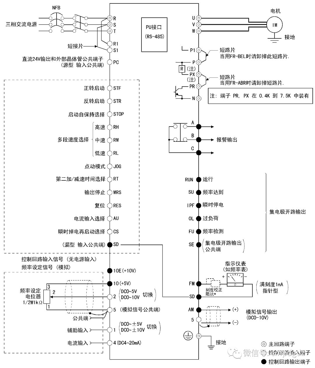
Overall wiring of the Mitsubishi FR-A540 inverter
The terminals of the inverter can be divided into main circuit terminals and control circuit terminals.
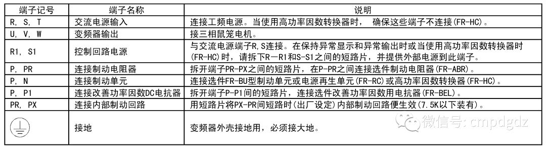
Main circuit terminal description
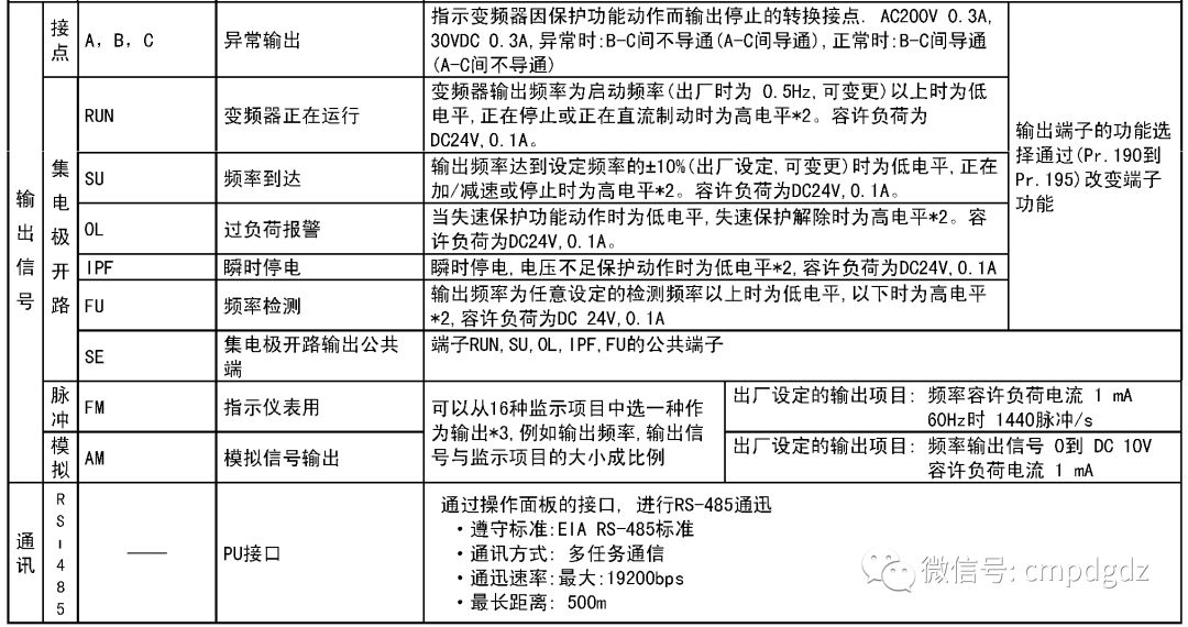

Control circuit terminal description
Main Circuit Wiring
The main circuit terminal block is shown in the figure below. The terminals R, S, and T are connected to the three-phase industrial frequency power supply; if connected to a single-phase industrial frequency power supply, it must connect to terminals R and S; terminals U, V, and W are connected to the motor; terminals P1, P, RP, PX, terminals R, R1 and S, S1 are connected using short-circuit bars; the grounding terminal is fixed with a screw and connected to the grounding wire.
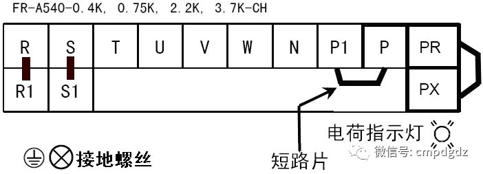
Main circuit terminal block
1. Main Circuit Wiring Principle
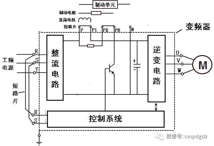
Main circuit wiring diagram
Terminals R, S, T connect to the industrial frequency power supply, and internally connect to the inverter rectifier circuit.
Terminals U, V, W connect to the motor, and internally connect to the inverter circuit.
Terminals P, P1 connect to short-circuit bars (or DC reactors to improve power factor), linking the rectifier circuit and inverter circuit.
Terminals PX, PR connect to short-circuit bars, linking internal braking resistors and braking control devices. If the internal braking resistor’s effect is not ideal, the short-circuit bar between terminals PX and PR can be removed, and an external braking resistor can be connected between terminals P and PR.
Terminals P and N are the positive and negative terminals of the internal DC voltage, respectively. To enhance braking capability during deceleration, the short-circuit bar between terminals PX and PR can be removed, and a dedicated braking unit (i.e., braking circuit) can be connected between terminals P and N.
Terminals R1 and S1 connect to the control circuit internally, and externally connect through short-circuit bars to terminals R and S. The power supply at terminals R and S is provided to the control circuit as power through short-circuit bars from terminals R1 and S1. If it is desired for the control circuit to operate without industrial frequency power input at terminals R, S, T, the short-circuit bars between R, R1 and S, S1 can be removed, and two-phase industrial frequency power can be directly connected to terminals R1 and S1.
2. Connection of Power Supply, Motor and Inverter
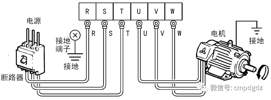
Connection of power supply, motor and inverter
When connecting, ensure that the power supply line is absolutely not connected to terminals U, V, W, otherwise it will damage the internal circuit of the inverter. Since the inverter may leak electricity during operation, for safety, the grounding terminal should be properly connected to the grounding wire to discharge any leakage current from the inverter.
3. Connection of Optional Components
The inverter has many optional components, mainly external braking resistors, FR-BU braking units, FR-HC power factor improving rectifiers, FR-RC energy feedback units, and DC reactors to improve power factor. Below, we will first introduce the connection of commonly used external braking resistors and DC reactors; for other optional components, please refer to the Mitsubishi FR-A540 inverter user manual.
(1) Connection of External Braking Resistors
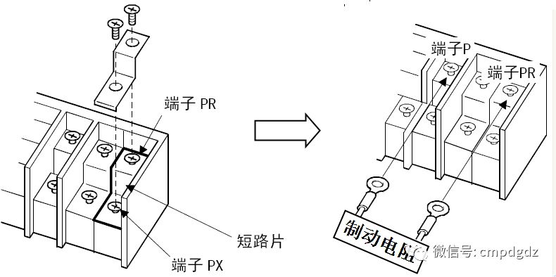
Connection of external braking resistors
First, remove the short-circuit bar between terminals PR and PX, then use connecting wires to connect the braking resistor to terminals PR and P.
(2) Connection of DC Reactors
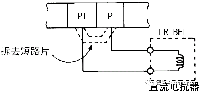
Connection of DC power factor reactors
First, remove the short-circuit bar between terminals P1 and P, then use connecting wires to connect the DC reactor to terminals P1 and P.
4. External Power Supply Wiring for Control Circuit
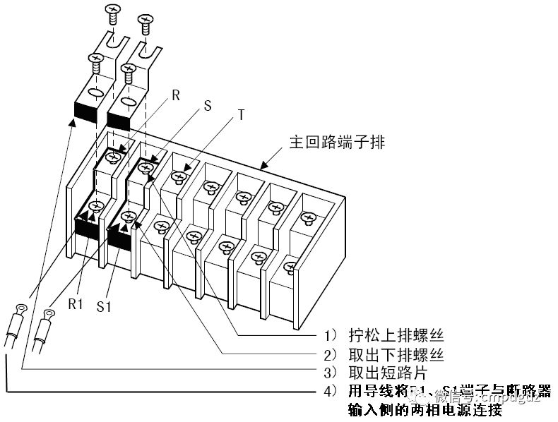
External power supply wiring for the control circuit
The control circuit power terminals R1 and S1 are normally connected to terminals R and S. During operation, if the inverter encounters an anomaly, it may cause the circuit breaker (or contactor) at the inverter power input terminal to trip, which will also disconnect the power supply to the control circuit, preventing the inverter from outputting abnormal display signals. To maintain the abnormal signal when needed, the control circuit’s power terminals R1 and S1 can be connected to the two-phase power lines on the input side of the circuit breaker, so that when the circuit breaker trips, the control circuit still has power supply.
Control Circuit Wiring
1. Control Circuit Terminal Block
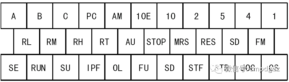
Control circuit terminal block
2. Changing Control Logic
The FR-A540 inverter has two types of control logic: sinking and sourcing logic, set to sinking logic at the factory. If you want to change the inverter’s control logic to sourcing logic, follow the steps in the figure below:
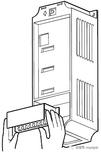
Remove the front cover of the inverter.
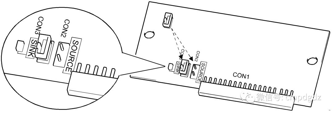
Loosen the screws of the control circuit terminal block, remove the terminal block; on the back of the control circuit terminal block, remove the short-circuit bar on the control logic setting jumper, and install it on the adjacent jumper.
This changes the inverter’s control logic from sinking control to sourcing control.
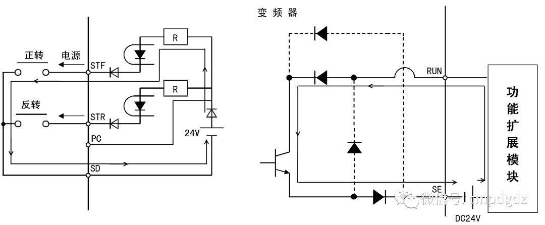
Typical wiring diagram of the inverter working in sinking control logic
In the diagram, the forward rotation button is connected between terminals STF and SD. When the forward rotation button is pressed, the internal power of the inverter generates current flowing out from terminal STF, through the forward rotation button, and back to the negative terminal of the internal power from terminal SD. The current path is shown in the diagram. Additionally, when the internal transistor collector open-circuit output of the inverter needs an external circuit, terminal SE must be used as a common terminal, and the current of the external circuit flows from the corresponding terminal (such as the RUN terminal in the diagram) into the internal transistor and finally flows out from terminal SE, as indicated by the arrows in the diagram. The diode connected by the dashed line in the diagram indicates that it is not conducting under sinking control logic.
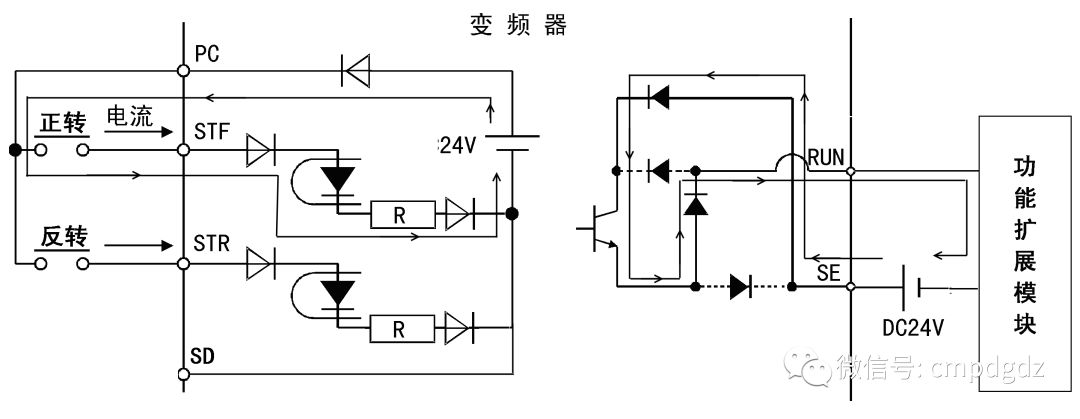
Typical wiring diagram of the inverter working in sourcing control logic
In the diagram, the forward rotation button needs to be connected between terminals STF and PC. When the forward rotation button is pressed, the internal power of the inverter generates current flowing out from terminal PC, through the forward rotation button, and back to the negative terminal of the internal power from terminal STF. The current path is shown in the diagram. Additionally, when the internal transistor collector open-circuit output of the inverter needs an external circuit, terminal SE must be used as a common terminal, and the current must flow in from terminal SE, passing through the internal transistor and finally flowing out from the corresponding terminal (such as the RUN terminal in the diagram), as shown by the arrows in the diagram. The diode connected by the dashed line in the diagram indicates that it cannot conduct under sourcing control logic.
3. Usage of STOP, CS, and PC Terminals
(1) Usage of STOP Terminal
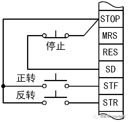
Wiring diagram for self-holding start signal (sinking logic)
This terminal is used when stop control is needed.
The stop button in the above diagram is a normally closed button. When the forward rotation button is pressed, current flows out from terminal STF, following this path: STF terminal out → forward rotation button → STOP terminal → stop button → SD terminal in, indicating that terminal STF has output current, which means there is a forward rotation command input, and the inverter outputs forward rotation power to the motor, allowing the motor to rotate forward. When the forward rotation button is released, terminal STF has no output current, and the motor stops. If the stop button is pressed, terminals STOP, STF, and STR will all be unable to output current, preventing the motor from starting.
(2) Usage of CS Terminal
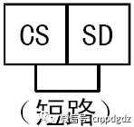
Short-circuiting terminals CS-SD
This terminal is used for momentary power loss restart and switching between industrial frequency power supply and inverter.
For example, during momentary power loss restart under sinking logic, first short-circuit terminals CS-SD as shown in the diagram, then set parameter Pr.57 to a momentary power loss restart free running time other than “9999”.
(3) Usage of PC Terminal
Using terminals PC and SD provides a DC 24V power supply externally, where PC is the positive terminal and SD is the negative terminal (common terminal). Terminal PC can provide a DC voltage of 18V to 26V, with a maximum current of 0.1A.
Connection of PU Interface
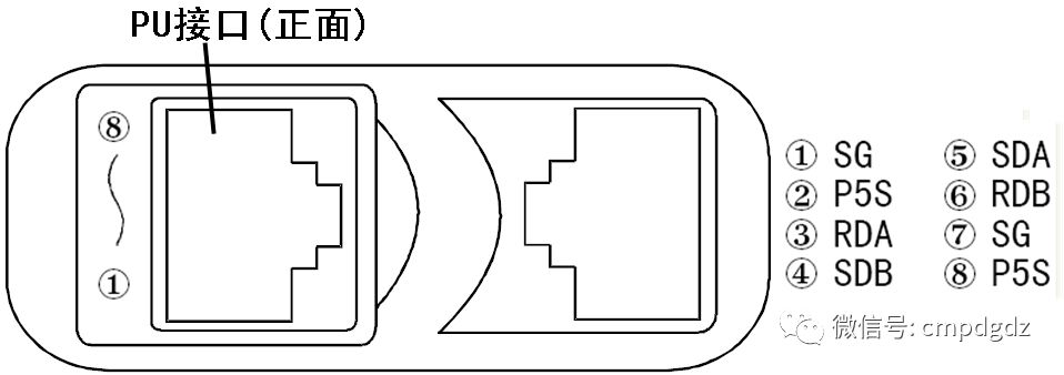
Appearance and pin definitions of PU interface
1. Connection of PU Interface with Computer with RS-485 Interface
When connecting a computer to a single inverter, the connection of the PU interface is as shown in the diagram below. When connecting, both the computer’s RS-485 interface and the inverter’s PU interface use RJ45 connectors (commonly known as crystal heads), and the connecting wire in between uses 10BASE-T cable (such as twisted pair cable used for computer networking).
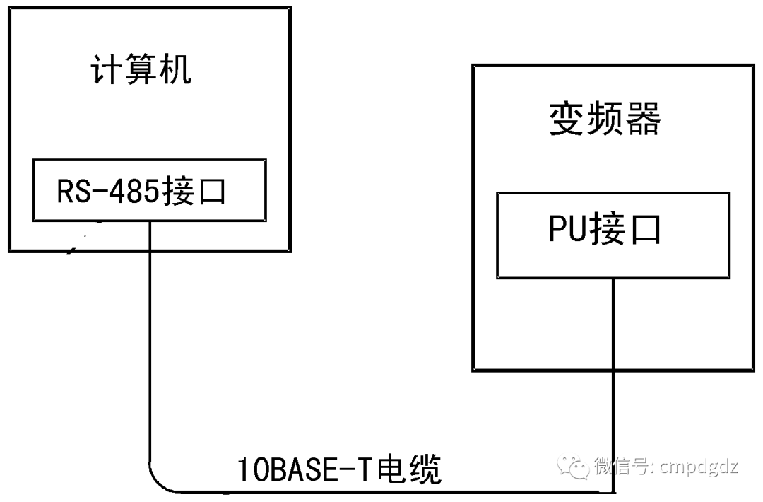
Connection of computer to a single inverter PU interface
The wiring method for the PU interface and RS-485 interface is shown in the diagram below. Since pins ② and ⑧ of the PU interface are used to provide power to the operation panel, these pins are not used during RS-485 communication with the computer.
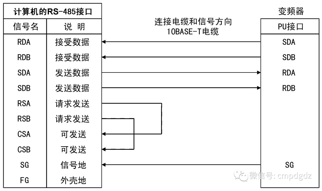
Wiring method for PU interface and RS-485 interface
When connecting multiple inverters to a computer, the connection is shown in the diagram below. The function of the distributor in the diagram is to split one signal into multiple signals. Additionally, due to transmission speed and distance, signal reflection may cause communication obstacles; therefore, it is advisable to install a terminal impedance resistor (100Ω) on the last inverter’s distributor.
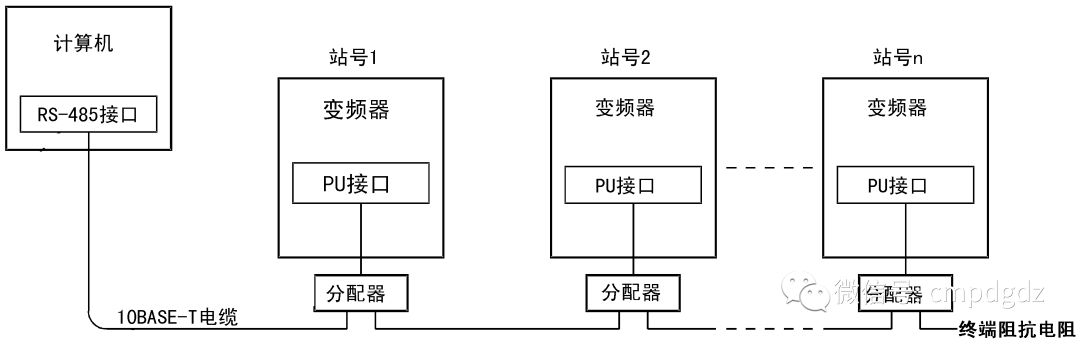
Connection of computer to multiple inverters
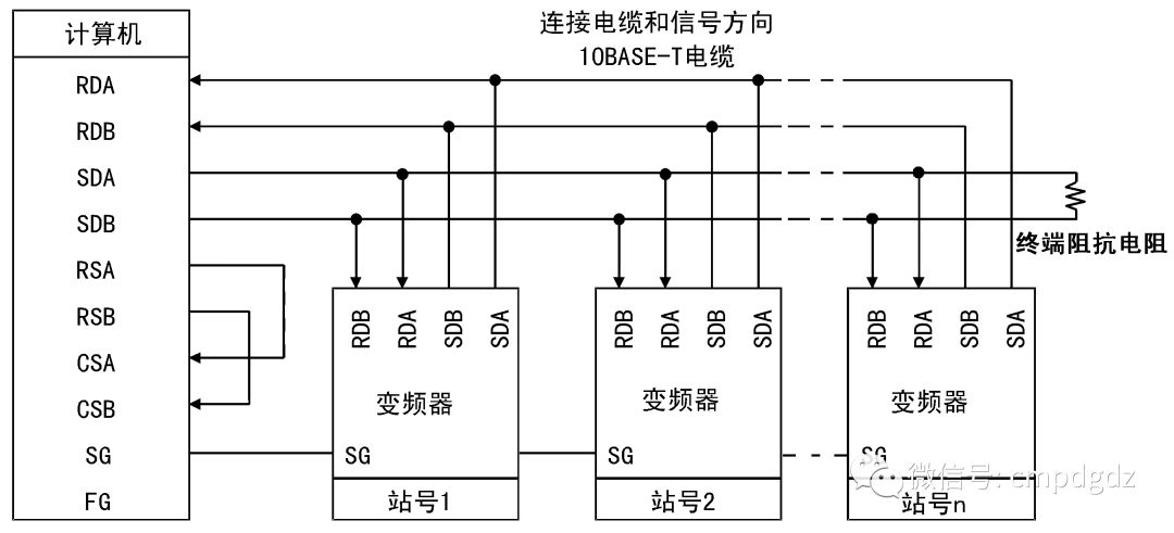
Wiring method for connecting computer to multiple inverters
2. Connection of PU Interface with Computer with RS-232C Interface
Since most computers do not have RS-485 interfaces but many have RS-232C interfaces (serial ports, also known as COM ports), to enable computers with RS-232C interfaces to connect to the PU port, an RS-232C to RS-485 interface converter can be used.
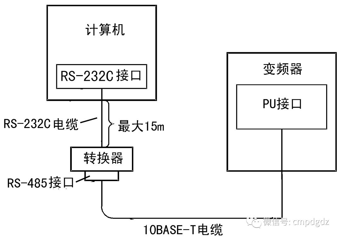
Connection of PU interface with computer with RS-232C interface
END
This article is original; please contact the editor for reprinting.
Please help improve the above content and discuss to enhance knowledge. At the same time, everyone is welcome to join our WeChat group. Please add the editor on WeChat, and we will invite you to join the group.
Recommended Books
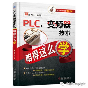
Click the image to quickly purchase the book
A beginner’s book on PLC and inverter technology, covering fast entry into Mitsubishi FX series PLCs, typical control circuits and parameter settings for inverters, comprehensive application of PLC and inverters, selection, installation, and maintenance of inverters, etc.