Difference Between RS232 and RS485 Interfaces
1. Physical Structure of the Interface
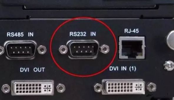
1. RS232 Interface
One of the computer communication interfaces, typically the RS-232 interface appears in the form of 9 pins (DB-9) or 25 pins (DB-25). Generally, personal computers have two sets of RS-232 interfaces, referred to as COM1 and COM2.
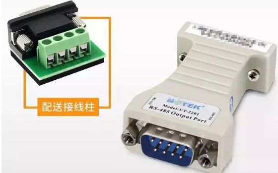
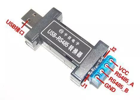
RS485 does not have a specific physical shape and is used based on the actual engineering situation.
2. Electronic Characteristics of the Interface
1. RS232
The signal level values of the transmission level signal interface are relatively high (signal “1” is “-3V to -15V”, signal “0” is “3 to 15V”), which can easily damage the interface circuit chip. Additionally, due to incompatibility with TTL levels (0~”<0.8v”, 1~”>2.0V”), a level conversion circuit is required to connect with TTL circuits. Moreover, it has poor anti-interference capability.
2. RS485
The differential signal logic “1” is represented by the voltage difference between the two wires as + (2—6) V; logic “0” is represented as – (2—6) V. The interface signal level is lower than that of RS-232, making it less likely to damage the interface circuit chip, and this level is compatible with TTL levels, facilitating connection with TTL circuits.
3. Communication Distance
1. RS232
RS232 has a limited transmission distance, with a maximum standard transmission distance of 15 meters, and can only communicate point-to-point, with a maximum transmission speed of 20kB/s.
2. RS485
RS485 has a maximum wireless transmission distance of 1200 meters. The maximum transmission speed is 10Mbps, and to achieve the maximum communication distance, a transmission speed of 100Kb/S is required. By using impedance-matched, low-loss dedicated cables, it can reach up to 1800 meters! Beyond 1200 meters, repeaters can be added (up to 8), making the transmission distance close to 10Km.
4. Support for Multi-point Communication
1. RS232
The RS232 interface only allows one transceiver to be connected to the bus, and cannot support multi-station transceiver capability, so it can only communicate point-to-point and does not support multi-point communication.
2. RS485
The RS485 interface allows up to 128 transceivers to be connected to the bus. This means it has multi-station communication capability, allowing users to easily establish a device network using a single RS485 interface.
5. Differences in Communication Cables
1. RS232
Can use three-core twisted pair, three-core shielded cable, etc.
2. RS485
Can use two-core twisted pair, two-core shielded cable, etc. In low-speed, short-distance, and interference-free situations, ordinary twisted pair can be used; conversely, for high-speed, long-distance transmission, dedicated RS485 cables (generally 120Ω) must be used (STP-120Ω for RS485 & CAN, one pair 18AWG), and in environments with severe interference, armored twisted shielded cables (ASTP-120Ω for RS485 & CAN, one pair 18AWG) should be used.
Supplement: Since the transmission distance of RS232 is only 15 meters, what is its use?
In fact, its applications are very broad, as it can connect various devices, such as monitoring and upgrading or debugging other devices. Its functionality is quite similar to USB, and with the increasing prevalence of USB ports, more devices that convert USB to RS-232 or other interfaces will emerge.
More RS-232 devices can be connected through USB, which not only achieves higher transmission speeds, realizing true plug-and-play but also solves the disadvantage of USB interfaces not being able to transmit over long distances (USB communication distance is within 5 meters).
Several Common Communication Protocols
Before starting this topic, we should understand a previous confusion I had.
Difference Between RS485 and MODBUS
RS485 is a physical interface, simply put, it is hardware.
MODBUS is an international standard communication protocol used for data exchange between devices from different manufacturers (generally for industrial purposes); the so-called protocol can also be understood as the “language” mentioned by someone above, simply put, it is software.
Generally, two devices transmit data through the MODBUS protocol: initially, RS232 was used as the hardware interface (the serial communication port on ordinary computers); there are also RS422 and commonly used RS485. This interface is used more often in general industrial sites due to its long transmission distance.
MODBUS protocol is divided into three modes: MODBUS RTU, MODBUS ASCII, and the later developed MODBUS TCP.
Among them, the first two (MODBUS RTU, MODBUS ASCII) use serial communication (RS232, RS422, RS485) for the physical hardware interface. MODBUS TCP, however, was developed to align with the current global trend, where everything can be connected via Ethernet or the Internet to transmit data. Thus, the MODBUS TCP mode was born, with the hardware interface being Ethernet (the network port commonly used on our computers).
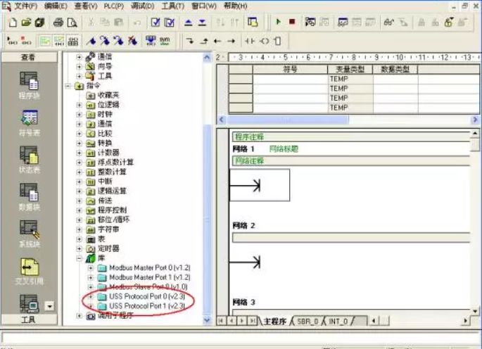
Then we can understand the various communication protocols supported by the S7-200 PLC through an image.
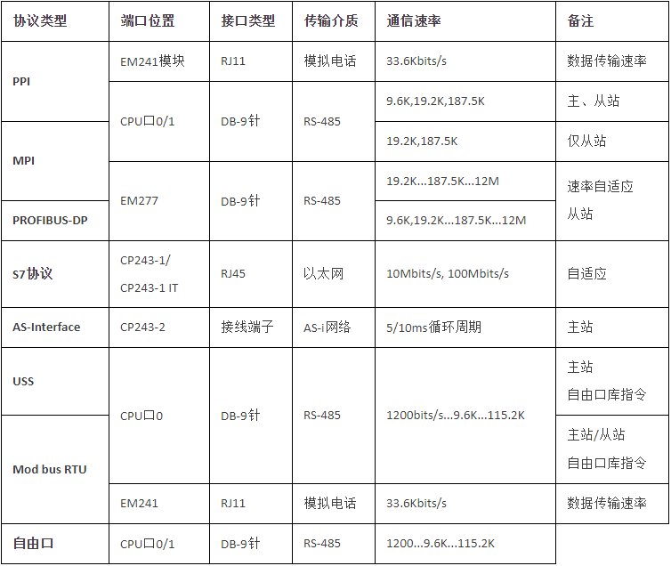
1. PPI Communication
This is a communication protocol developed by Siemens specifically for the S7-200 series PLC. It is embedded in the S7-200 CPU. The PPI protocol is physically based on the RS-485 port and can achieve PPI communication through shielded twisted pair. PPI protocol is a master-slave protocol. The master device sends requests to the slave device, and the slave device responds; the slave cannot actively send information. The master station communicates with the slave via a shared connection managed by the PPI protocol. The PPI protocol does not limit the number of masters that can communicate with any slave; however, in a network, the number of masters cannot exceed 32. The most basic use of the PPI protocol is to allow Siemens Step7-Micro/Win programming software to upload and download programs and to communicate with Siemens human-machine interfaces and PCs.
2. MPI Communication
MPI (multipoint interface) is the interface for SIMATIC S7 multi-point communication, suitable for communication between a small number of stations, mainly used for close-range communication between upper computers and a few PLCs. By connecting the MPI programming port of the S7-300 or S7-400 CPU with the PPI communication port of the S7-200 CPU via Profibus cables and connectors, and connecting to the programming port (MPI/DP port) of the upper computer network card via Profibus or MPI cables, communication can be achieved. Of course, the network can also exclude the PC and only include PLCs.
The communication rate of MPI is 19.2k~12mbit/s, but the maximum speed of the MPI network directly connected to the S7-200 CPU communication port is usually limited to 187.5kbit/s (due to the limitation of the S7-200 CPU’s maximum communication rate). A maximum of 32 stations can exist on the MPI network, and the longest communication distance in one network segment is 50 meters (when the communication baud rate is 187.5kbit/s), and longer distances can be extended using RS-485 repeaters. MPI allows master-master communication and master-slave communication, with a maximum of 4 connections per S7-200 CPU communication port.
MPI protocol cannot communicate with an S7-200 CPU acting as a PPI master; when communicating between S7-300 or S7-400 and S7-200, the S7-200 CPU must not act as a PPI master. Micro/Win cannot access an S7-200 CPU acting as a PPI master via MPI protocol. The S7-200 CPU can only act as an MPI slave, meaning S7-200 CPUs cannot communicate with each other via the MPI network, only via PPI.
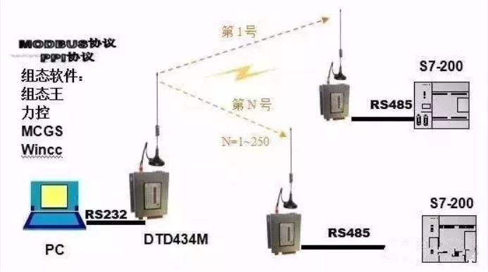
3. Modbus Communication
Modbus was invented by Modicon (now a brand of Schneider Electric) in 1979 and is the first truly industrial bus protocol used in the field. To better popularize and promote Modbus in distributed applications based on Ethernet, Schneider has transferred ownership of the Modbus protocol to IDA (Interface for Distributed Automation), establishing Modbus-IDA to lay the foundation for the future development of Modbus.
In China, Modbus has become a national standard GB/T19582-2008. According to incomplete statistics, by 2007, the number of Modbus nodes installed had exceeded 10 million.
The Modbus protocol is a universal language applied to electronic controllers. Through this protocol, controllers can communicate with each other and with other devices over a network (such as Ethernet). It has become a universal industrial standard. With it, control devices produced by different manufacturers can be connected into an industrial network for centralized monitoring. This protocol defines a message structure that a controller can recognize, regardless of the network used for communication.
It describes the process by which a controller requests access to other devices, how to respond to requests from other devices, and how to detect and log errors. It establishes a common format for the message domain structure and content. Modbus is a single-master master/slave communication mode. There can only be one master on a Modbus network, while there can be several slaves.
Modbus has the following characteristics:
1. Standard and open, users can freely and safely use the Modbus protocol without paying licensing fees or infringing intellectual property. Currently, more than 400 manufacturers support Modbus, and over 600 products support Modbus.
2. Modbus can support multiple electrical interfaces, such as RS-232, RS-485, etc., and can transmit over various media, including twisted pairs, fiber optics, and wireless.
3. The frame format of Modbus is simple, compact, and easy to understand. It is user-friendly and easy for manufacturers to develop.
Note: The S7-200 only supports the Modbus RTU protocol and does not support the Modbus ASCII protocol;
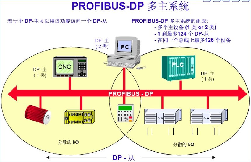
4. ProfiBus Communication
As one of the many fieldbus families, ProfiBus is the most widely used fieldbus standard in the European industry and is currently one of the internationally accepted fieldbus standards. ProfiBus belongs to the unit-level, field-level SIMATIC network, suitable for transmitting small to medium amounts of data. Its openness allows many manufacturers to develop their own products that comply with the ProfiBus protocol, which can be connected to the same ProfiBus network.
ProfiBus is an electrical network, with physical transmission media that can be shielded twisted pairs, fiber optics, or wireless transmission. It officially became an international standard for fieldbus in 1989. PROFIBUS is an international, open, device-independent fieldbus standard, with transmission speeds selectable within the range of 9.6kbaud to 12Mbaud; when the bus system starts, all devices connected to the bus should be set to the same speed.
PROFIBUS is widely used in manufacturing automation, process industry automation, and automation in other fields such as buildings and transportation power. PROFIBUS is also a fieldbus technology used for workshop-level monitoring and data communication and control at the field device layer. It enables distributed digital control and field communication networks from the field device layer to workshop-level monitoring, providing feasible solutions for comprehensive factory automation and intelligent field devices.
5. USS Communication
USS (Universal Serial Interface) is a communication protocol developed by Siemens specifically for drive devices, which has undergone continuous development and improvement over the years. Initially, USS was used for parameterizing drive devices, focusing more on parameter settings. It is widely used in connections between drive devices and operator panels or debugging software (such as DriveES/STARTER).
Recently, due to its simple protocol and low hardware requirements, USS has increasingly been used for communication with controllers (such as PLCs) to achieve general-level communication control. (Note: USS provides a low-cost, relatively simple communication control method, but due to its design, USS cannot be used in scenarios with high communication rate and data transmission requirements.
In scenarios with high communication requirements, a communication method with better real-time performance, such as PROFIBUS-DP, should be chosen. During system design, this limitation of USS must be considered.
For example, if USS communication control is used for a dozen or even dozens of frequency converters in applications requiring high speed synchronization (such as paper production lines), the effect can be imagined.
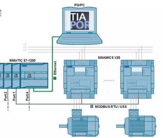
All Siemens frequency converters have an RS485 communication port, with the PLC as the master station, allowing up to 31 frequency converters as slaves in the communication loop. Based on the address of each frequency converter or using broadcast methods, the required frequency converters can be accessed. Only the master station can send communication request messages, and the address character in the message specifies which slave to transmit data to; the slave can only send data to the master station after receiving the master station’s request message, and slaves cannot directly exchange data with each other.
Before using the USS protocol, the Siemens instruction library must be installed. The USS protocol instructions are in the library folder of the STEP7-MICRO/WIN32 instruction tree, providing 14 subprograms, 3 interrupt programs, and 8 instructions to support the USS protocol. When an instruction is called, one or more subprograms will be automatically added.
The basic characteristics of the USS protocol are as follows:
● Supports multi-point communication (thus can be used on networks such as RS 485)
● Uses a single master “master-slave” access mechanism
● A maximum of 32 nodes can exist on a network (maximum of 31 slaves)
● Simple and reliable message format, making data transmission flexible and efficient
● Easy to implement, with low cost
The working mechanism of USS is that communication is always initiated by the master station, which continuously polls each slave. Each slave decides whether and how to respond based on the received instructions. Slaves never actively send data.
Slaves should respond under the following conditions:
1. The received master message has no errors;
2. And this slave is addressed in the received master message.
-
(Content sourced from the internet, copyright belongs to the original author)
-
Disclaimer: If copyright issues arise, please contact for removal! Neither individuals nor institutions bear any legal responsibility.
-