This section continues to discuss another serial communication interface in embedded hardware communication protocols – IIC. Compared to UART serial protocol and SPI serial peripheral interface protocol, IIC has its unique features.
-
Introduction
IIC (Inter-Integrated Circuit), integrated circuit bus.
IIC stands for Inter-Integrated Circuit (integrated circuit bus), this type of bus was designed by Philips Semiconductor in the early 1980s as a simple, bidirectional, two-wire synchronous serial bus, mainly used to connect integrated circuits (ICs). IIC is a multidirectional control bus, meaning multiple chips can connect to the same bus structure, and each chip can act as a control source for real-time data transmission. This method simplifies the signal transmission bus interface.
–from Baidu Encyclopedia
https://baike.baidu.com/item/iic/3524834
Compared to the SPI interface, as discussed in Embedded Hardware Communication Interface Protocol – SPI (Part 1) Basics, the IIC interface defines a multi-master, multi-slave communication architecture, allowing multiple masters and multiple slaves on the same IIC bus. The “Master ->Slave” communication architecture gives the active control to the master, which initiates communication while the slave responds.
-
Signal Lines
IIC as a two-wire serial bus has the following signal lines:
SCL (Serial Clock Line): serial clock, output by the master
SDA (Serial Data Line): serial data, bidirectional transmission
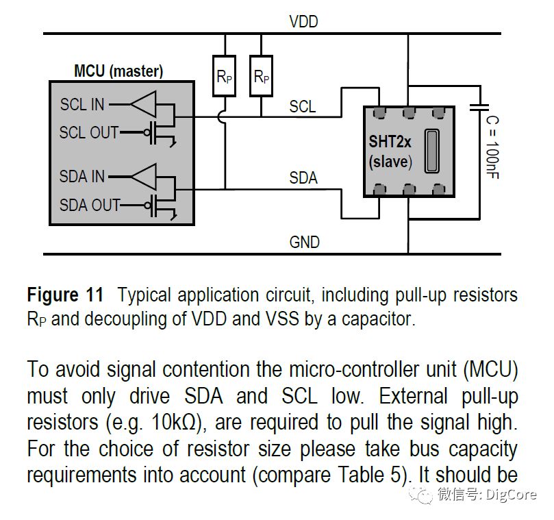
The bus signal levels in circuit connections typically include pull-up resistors Rp, ensuring that the bus remains in a high level state when idle.
This can be specifically found in some chip manuals, explicitly stating the pull-up resistor requirements for line connections:
SHT20 humidity and temperature sensor requires pull-up resistors:
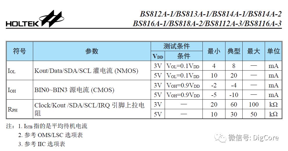
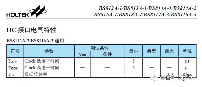
In the BS116A-3 touch key chip data manual:
-
Signal Timing
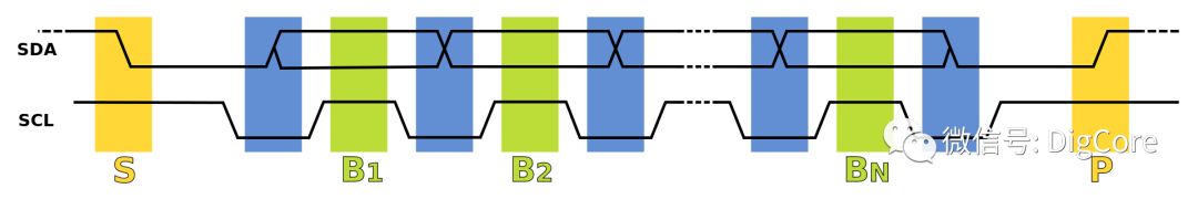
IIC as a synchronous serial bus can be considered to have two synchronization signals, the first is the start and stop flag for communication, informing the slave devices on the IIC bus when to start and end communication; the second is the synchronous clock signal SCL, during data interaction, both parties transmit and sample data based on the transitions of SCL.
-
Start Flag
When idle, both SCL and SDA are high level; at a certain moment, if SDA is pulled low, it is considered the start of IIC transmission.
-
End Flag
When data transmission is about to complete, if SCL is high, pulling SDA high indicates the end of IIC transmission.
-
Data Output
When SCL is low, the sender changes the level of SDA bit by bit based on the data content being transmitted.
-
Data Sampling
When SCL is high, the receiver reads the level of SDA bit by bit and assembles them into 1 Byte.
-
ACK Response
ACK indicates that after 8 bits of data, during the high level of the 9th clock, SDA remains low.
-
NACK Response
NACK indicates that after 8 bits of data, during the high level of the 9th clock, SDA remains high.
For understanding and memorization, it is recommended to group memory:
When SCL is high, SDA pulled low indicates the start, SDA pulled high indicates the end;
When SCL is high, the receiver samples the SDA pin level; when SCL is low, the sender changes the SDA pin level;
The ACK bit, SDA low indicates ACK, SDA high indicates NACK.
The above describes the possible signal timing state characteristics of IIC during communication.
If we compare with the SPI interface, we find that when multiple slave devices are connected to the IIC bus, at a certain moment when a master wants to communicate with a specific slave, unlike the SPI which has a dedicated chip select signal pin SS.
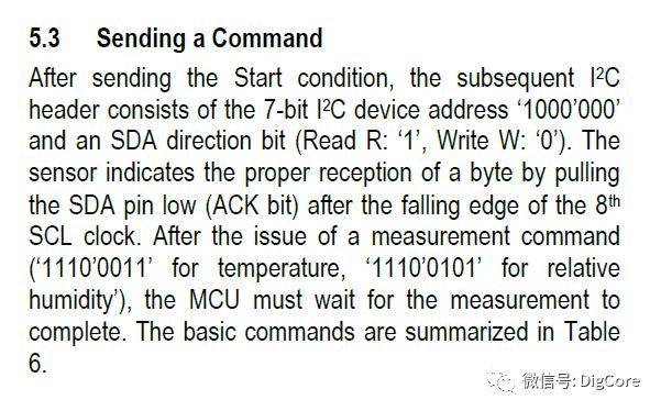
Thus, for IIC to achieve communication between the master and the designated slave, the master must first send the address of the designated slave device through the interface each time communication starts, allowing the corresponding slave device to be selected for subsequent communication operations.
Similarly, each peripheral device with an IIC interface has address configuration in its data manual:
SHT20 humidity and temperature chip address configuration:
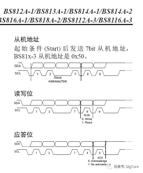
BS116-3 touch chip address configuration:
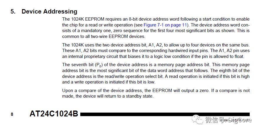
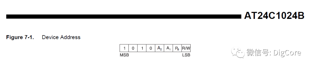
AT24C1024B storage chip:
We find that the addresses of IIC devices are generally 7bit, and each data transmission is sent as one byte 8bit, so when sending addresses, they will include the read/write bit, forming one byte for transmission.
The significance of the read/write bit is mainly to clarify for the IIC slave device, after being “called out” by the master, whether it will be read or written by the master, which is determined by this read/write bit.
Additionally, similar to the AT24C1024B storage chip, within the 7bit address bits, there are 3 additional bits A2, A1, A0 that can be selected for different connection methods on the hardware circuit, resulting in 8 different slave addresses, meaning multiple AT24C1024B storage chips of the same model can be connected to the same IIC bus.
-
Interface Configuration Items
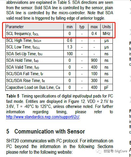
Compared to the rich configuration items of the SPI interface, the IIC only has 2 data lines, and the only configurable item is the clock SCL flip rate, as this clock rate directly affects the data transmission rate.
The recommended values for configuration should confirm the rate limits of each slave device on the IIC bus, ensuring that the design of the IIC interface can accommodate the communication rates of all devices on the bus.
SHT20 humidity and temperature sensor:
BS116-3 touch chip clock limit:
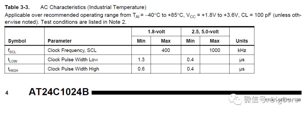
AT24C1024B storage chip clock requirements:
In summary, the IIC bus interface is a two-wire, multi-master, multi-slave, half-duplex communication interface protocol. Familiarity with the timing diagrams of the two signal lines provides a basic understanding of IIC.
Stay tuned for future updates on the layered architecture design of the IIC interface.
★★★★★ Recommended Articles
“【Embedded Programming】Function Return Type Design”
“【Embedded Programming】Solutions for Platform Endianness Storage Differences”
“Embedded Hardware Communication Interface – Using RingBuffer to Process Data (Part 2) Detailed Design Process”
“Embedded Hardware Communication Interface – Using RingBuffer to Process Data (Part 1)”
“Rapid Development of MQTT (Part 1) MQTT from an Electronics Engineer’s Perspective”
“Rapid Development of MQTT (Part 2) Introduction to MQTT”
“Building MQTT Client – The Clearest MQTT Protocol Architecture”
“Setting Up MQTT Server – The Fastest Way to Validate Your Developed Client”
★★★★★ Similar Articles
“Embedded Hardware Communication Interface Protocol – UART (Part 5) Data Packet Design and Analysis”
“Embedded Hardware Communication Interface Protocol – UART (Part 4) Designing Start-Stop Application Layer Protocol”
“Embedded Hardware Communication Interface Protocol – UART (Part 3) Quick Use of Serial Port and Applications”
“Embedded Hardware Communication Interface Protocol – UART (Part 2) Standards under Different Electrical Specifications”
“Embedded Hardware Communication Interface Protocol – UART (Part 1) Basics”
“Embedded Hardware Communication Interface Protocol – SPI (Part 2) Layered Architecture Design of Simulated Interface”
“Embedded Hardware Communication Interface Protocol – SPI (Part 1) Basics”
★★★★★ Extended Reading
“【Hardware Circuit】Altium Designer 18 Rule Check Definitions”
“【Hardware Circuit】Basic Principles and Application Cases of N-channel and P-channel MOSFETs”


www.digcore.cn
More technical content awaits you
Long press the QR code to follow