Using S7-200 to achieve automatic control of the car moving back and forth. The control process is pressing the start button, the car moves from left to right (and back from right to left). When it reaches the right (or left) limit switch, the car automatically returns. When it hits the other limit switch, it returns again. This back-and-forth motion continues until the stop button is pressed, at which point the car stops moving.
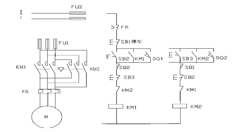
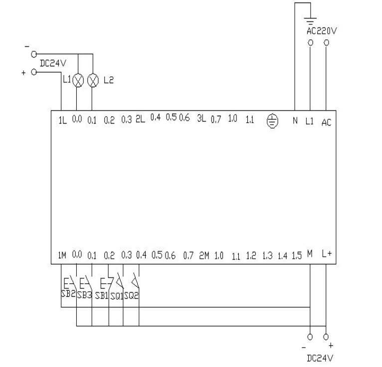
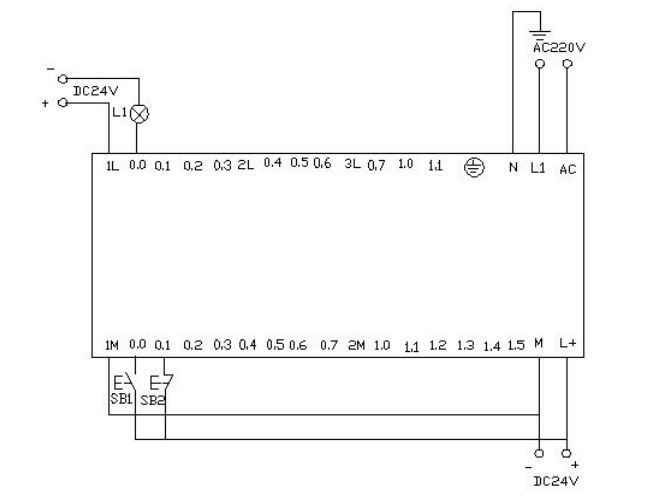
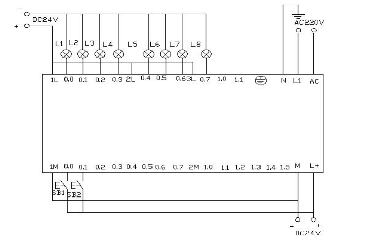
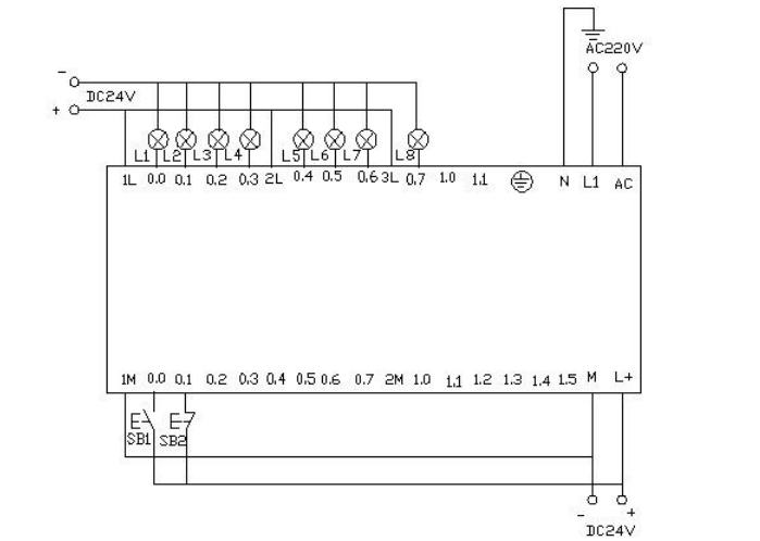
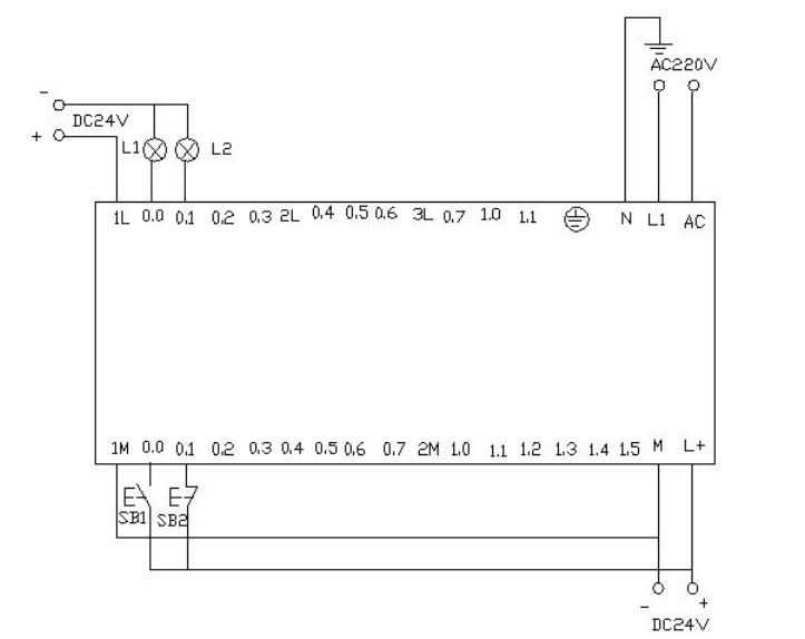
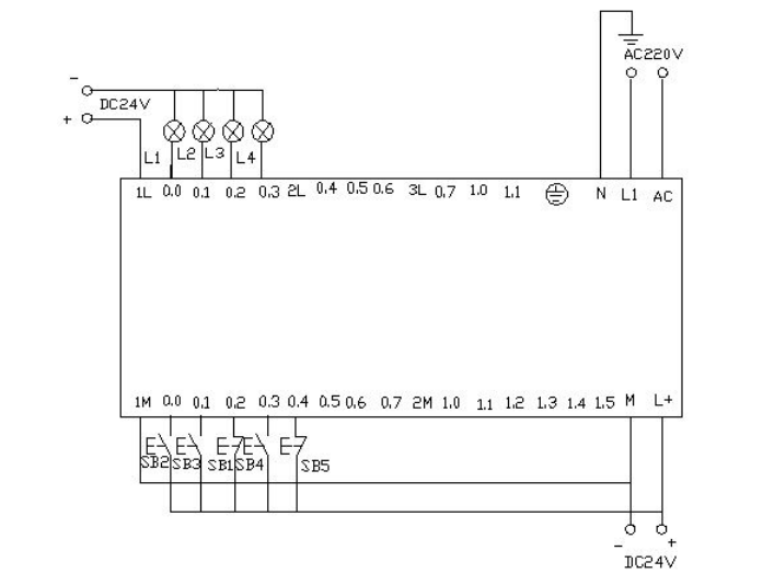
▲ Electrical Wiring Diagram


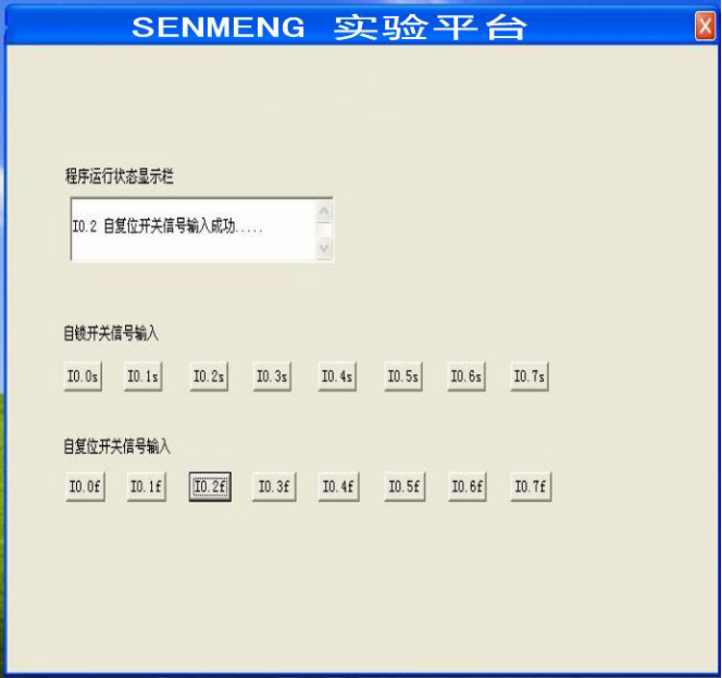
▲ Control Platform Operation Panel
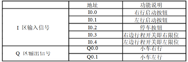
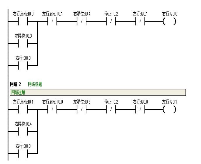
When pressing SB2, i0.0 (mouse click i0.0f) is activated, Q0.0 is activated, and the car moves to the right (indicated by the light Q0.0). When the car encounters the right limit switch SQ2, i0.4 (simulated by mouse click i0.4f), it activates, and the car moves left (the light Q0.0 goes out, and the light Q0.1 turns on). When it reaches the left limit SQ1, i0.3 (mouse click i0.3f), it activates, and the car moves to the right again (the light Q0.1 goes out, and the light Q0.0 turns on). This back-and-forth motion continues until SB1, i0.2 (mouse click i0.2f) is activated, stopping the car.
Appendix:
Pressing the start button requires that within two seconds, the light is on for one second and off for one second, repeating this cycle, making the light flash.
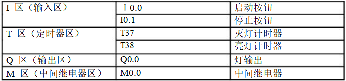
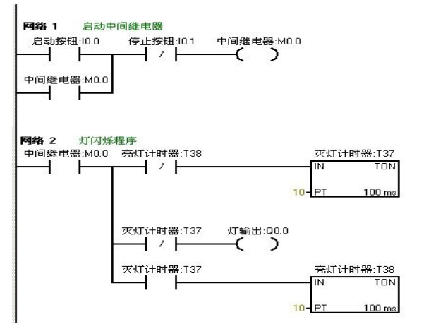


Download the written program to the Siemens S7-200 PLC for debugging. Observe whether the results match the experimental requirements. Debug through the online control panel. When i0.0f (i0.0 is activated) is pressed, Q0.0 outputs, and the light connected to Q0.0 turns on. At the same time, timer T37 starts timing. After one second, T37 operates, its normally closed contact opens, so Q0.0 has no output, and the connected light goes out. As the light goes out, timer T38 starts timing. After one second, the normally closed contact in series with timer T37 opens, so T37 resets, and its normally closed contact returns to normally closed. At this point, Q0.0 has output again, and the connected light turns on again. Thus, the light connected to output Q0.0 flashes on for one second and off for one second continuously until the online control panel button I0.1f (i0.1 is activated) is pressed, stopping the flashing circuit. If you want to change the flashing frequency of the light, you can achieve this by changing the timer’s timing.
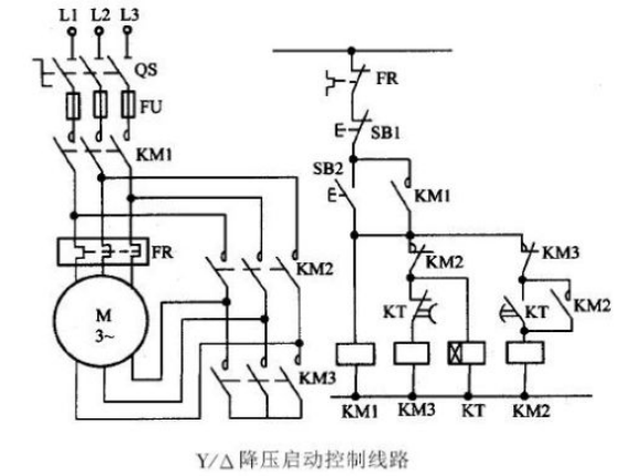
Using Siemens S7-200 PLC to achieve star-delta connection soft start.
Star-Delta Soft Start Circuit Diagram
Flow Framework Diagram as follows
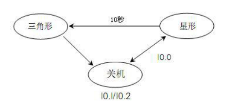
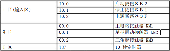
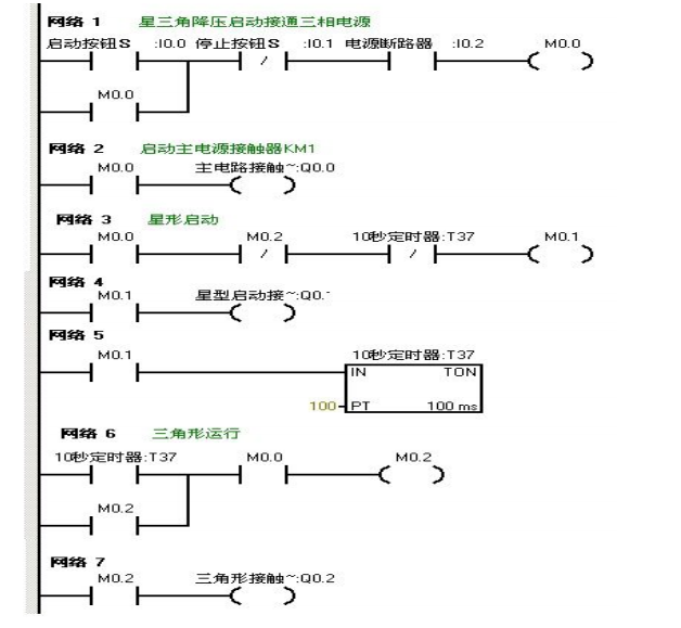
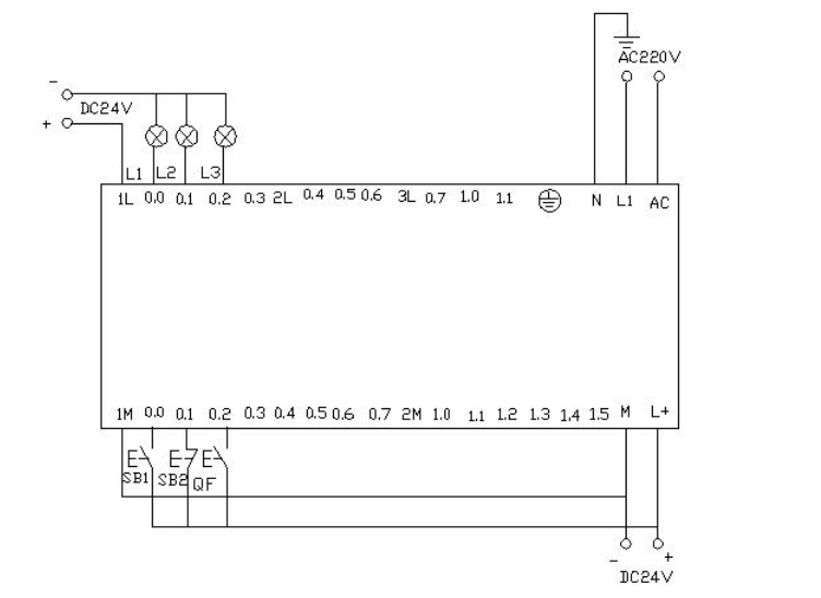


Download the written program to the Siemens S7-200 PLC for debugging. After downloading, we open the online control panel for debugging to see if the running results meet the requirements. First, set i0.2f on the control panel to indicate the button is pressed, meaning the circuit breaker QF is closed. Press the start button i0.0f (SB2), i0.0 is activated, the motor starts in star mode, Q0.0 and Q0.1 have output, indicating that the two lights L1 and L2 in the experimental wiring diagram are on, while driving the timer. When the timer counts to 10 seconds, it switches to delta start, at which point Q0.1 has no output, Q0.2 has output, meaning Q0.0 and Q0.2 have output, and the motor runs in delta mode. The lights L1 and L3 on the wiring panel are on. When pressing i0.1f on the online panel (i0.1 is activated), the motor stops running. All output points have no output.
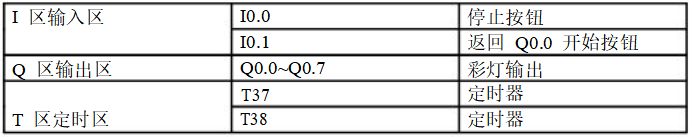
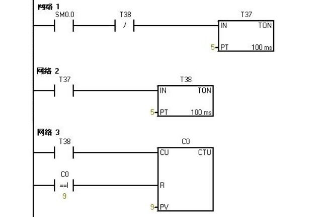
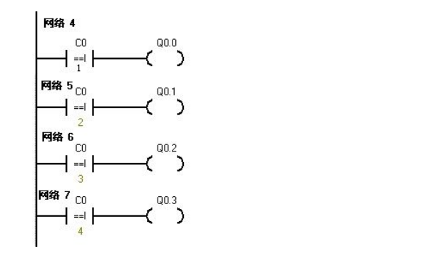
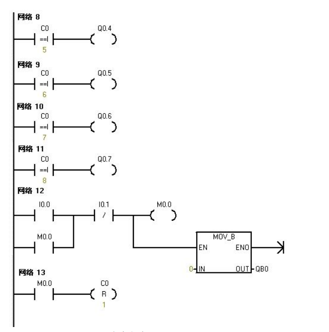
Using PLC’s Q0.0 to Q0.7 eight output terminals to control eight color lights, making each light turn on every second in a loop. When I0.0 is activated, all lights turn off. When I0.1 is activated, the cycle starts again from Q0.0.


Download the written program to the PLC for debugging. After downloading, we open the online control panel for debugging to see if the running results meet the requirements.
After powering up the PLC, SM0.0 remains activated. Therefore, T37 starts timing, and after the delay, T38 starts timing. After T38 times out, its normally closed contact opens, so T37 stops timing, and T37’s normally open contact returns to normally open, causing T38 to also stop timing. At this point, T38’s normally closed contact returns to normally closed, so T37 starts timing again, while counter C0 begins counting once. This cycle repeats. When the count is 1, Q0.0 activates. When the counter counts to 2, Q0.1 activates… and so on, when the counter reaches 8, Q0.7 activates. When the counter counts to 9, the counter C0 resets. When pressing I0.0f on the online control panel (i0.0 activates), all outputs Q0.0 to Q0.7 are reset to zero, and no lights are on. When pressing I0.1f on the online control panel (i0.1 activates), the counter starts counting again, and the lights turn on one by one starting from Q0.0.
Using IO wires to control eight color lights connected to Q0.0 to Q0.7, shifting every 0.5 seconds, initially setting Q0.0 and Q0.2 to output. Using I0.1 to control the direction of the color light shift.
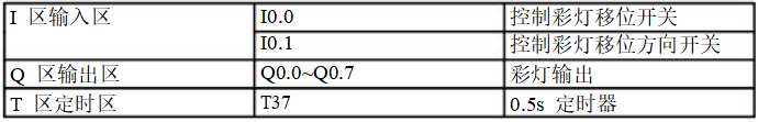
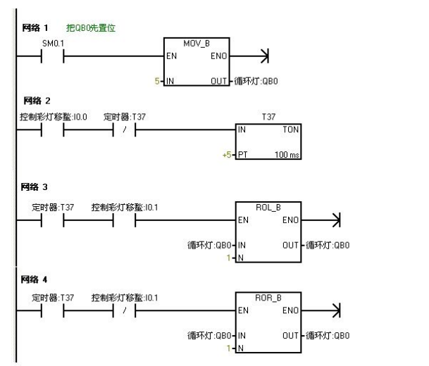


Download the program to the Siemens S7-200 PLC for debugging. When the PLC powers up, Q0.0 and Q0.2 will output, thus turning on Q0.0 and Q0.2. When the button on the online panel, I0.0f (indicating I0.0 input), is pressed, the timer T37 starts timing every 0.5 seconds, and the color lights will shift to the right each time. When the button I0.1f on the online control panel is pressed (indicating I0.1 input), the color lights will shift to the left in the same manner.
Using jump instructions to control two lights L1 and L2, connected to Q0.0 and Q0.1, with switch position I0.0, and control switches for the two lights at I0.1 and I0.2. In manual mode, the two lights are controlled separately with their respective control switches. In automatic mode, the two lights alternate every second.
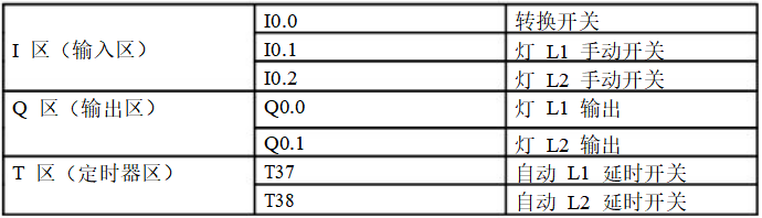
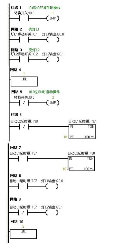


Download the completed program to the S7-200 PLC for debugging. When I0.0 is OFF, the PLC runs the manual program. Pressing the buttons I0.1f and I0.2f on the online control panel indicates (I0.1 and I0.2 are closed) that lights L1 and L2 are on, and Q0.0 and Q0.1 have output. When we press I0.0f on the online control panel, I0.0 is ON, and the program jumps to the automatic program. The two lights alternate every second, first L1 for one second, then L2. When pressing I0.0f on the online control panel again, I0.0 becomes OFF, and the program jumps back to manual operation.
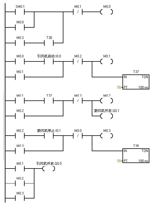
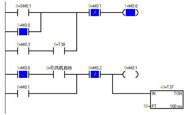
▲ Program Monitoring Screen When PLC is Powered On, Blue Indicates Activated


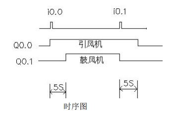
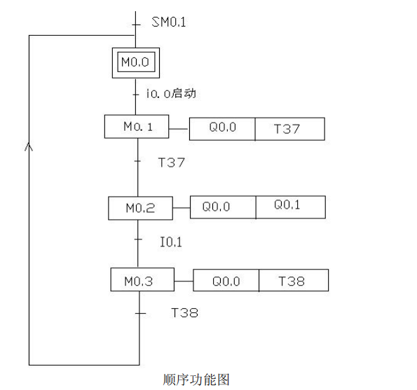
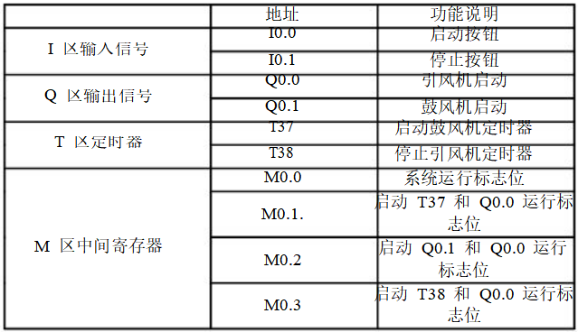
SM0.1 is activated in the first scan cycle and does not activate afterwards. When pressing I0.0f on the online control panel, i0.0 is activated, leading to Q0.0 output (indicating that the light Q0.0 is on) and starting the induced draft fan. At the same time, timer T37 activates and starts counting. When timer counts to 50 (indicating that light Q0.1 is on), the blower starts. At this point, both fans are running. When pressing I0.1f on the online control panel, the blower stops (indicating that light Q0.1 is off), and timer T38 activates and starts counting. After 5 seconds, the induced draft fan stops (indicating that light Q0.0 is off).
Using S7-200 to achieve automatic control of liquid mixing. When the start button is pressed, valve A opens, and liquid A flows into the mixer. When the liquid level reaches the middle limit, valve A closes, and valve B opens, allowing liquid B to flow into the mixer. When the liquid level reaches the upper limit, valve B closes, and the motor starts mixing. After one minute, the motor stops, and valve C opens, allowing the mixed liquid to flow out. When the liquid level reaches the lower limit, the container is emptied after 5 seconds, and valve C closes. Valve A opens, injecting liquid A. This cycle continues. If the stop button is pressed, the system must wait for one complete cycle to stop.
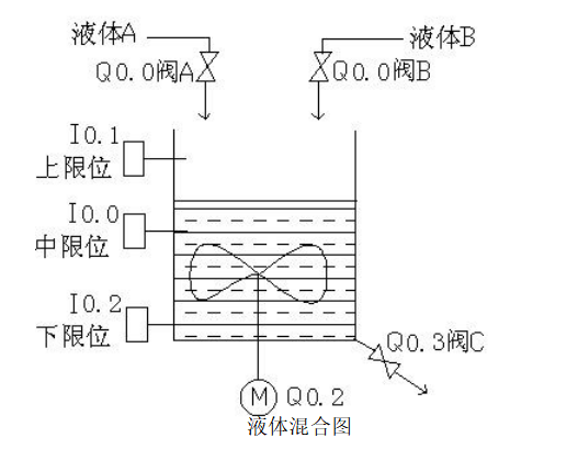
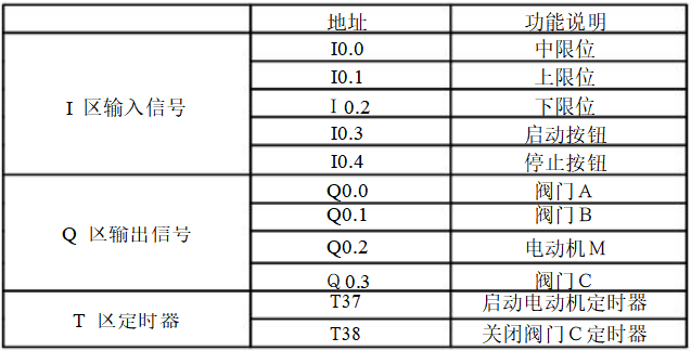
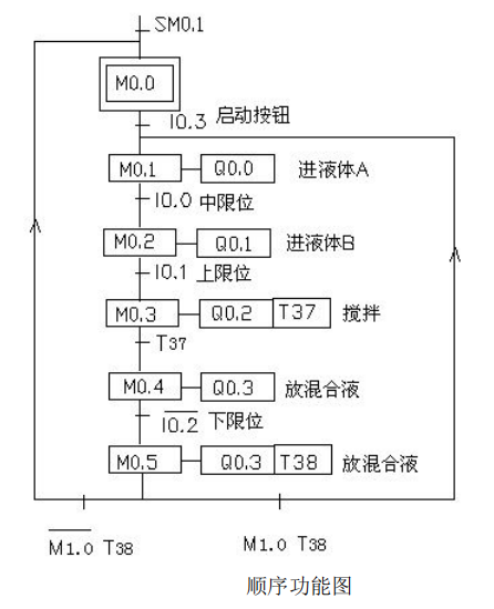
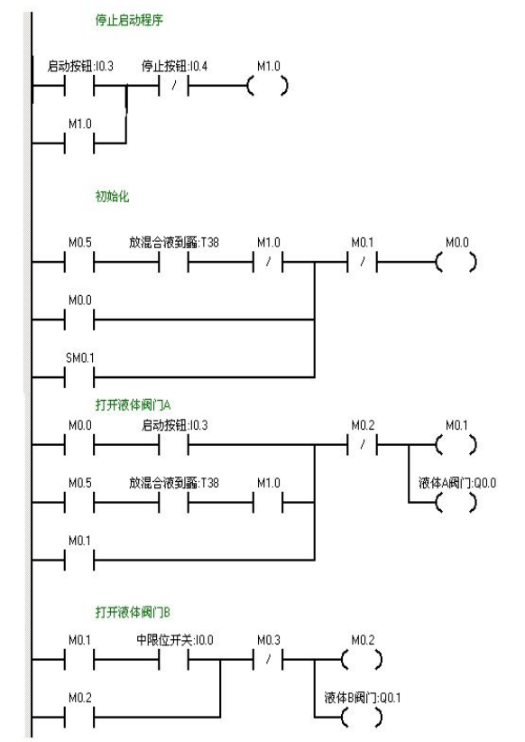
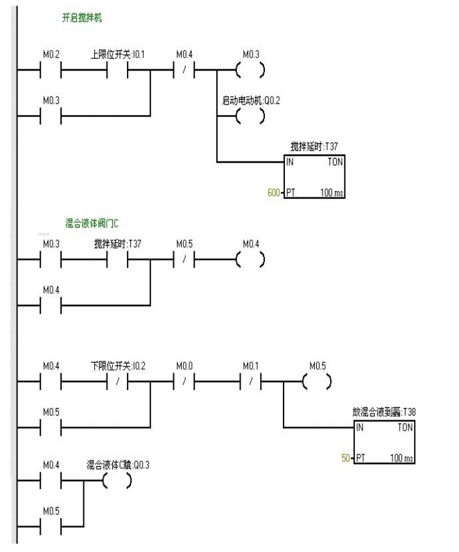


When pressing I0.03f on the online control panel (i0.3 is closed), valve A opens (Q0.0 is on). When pressing I0.0f on the online control panel (i0.0 middle limit is closed), valve A closes, and valve B opens (Q0.0 goes off, Q0.1 turns on). When pressing I0.1f on the online control panel (upper limit I0.1 is closed), valve B closes, and the motor starts stirring (Q0.1 goes off, Q0.2 turns on) while timer T37 starts timing for one minute. After one minute, the mixer stops stirring, and valve C opens (Q0.2 goes off, Q0.3 turns on). When the liquid level reaches the lower limit, valve C continues to open (Q0.3 turns on), while timer T38 starts timing. After 5 seconds, valve C closes, and valve A opens (Q0.3 goes off, Q0.0 turns on), entering the next cycle. Pressing I0.4f on the online control panel (indicating stop I0.4 is closed) does not stop the system immediately but waits until one cycle is completed before stopping.
Complete Question Bank for Electrical Worker Junior Exam 2021 (Including Answers)
Is troubleshooting inverter faults difficult? Just one click!
Can you sweep through all electrical exam questions with one click? Have you not owned this tool yet?
Which of the five major electrical drawing software (CAD, Eplan, CADe_simu…) do you choose?
The latest electrical version CAD drawing software, with super detailed installation tutorial!
The latest electrical drawing software EPLAN, with super detailed installation tutorial!
Common issues for beginners using S7-200 SMART programming software (includes download link)
Super comprehensive electrical calculation EXCEL sheets, automatically generated! No need to ask for electrical calculations!
Bluetooth headsets, electrical/PLC beginner books are randomly given away? Come and receive your electrical gift!
Basic skills in PLC programming: Ladder Diagram and Control Circuits (Includes 1164 practical cases for Mitsubishi PLC)
Still can’t understand electrical diagrams? Take away the basics of electrical diagram recognition and simulation software, quickly get started with theory and practice!
12 free electrical video courses, 10GB software/e-book materials, and 30 days of free live electrical courses are given away!