Imagine a DC power supply with an output socket that has three pins: positive, negative, and ground. Correspondingly, the load’s plug should also have three pins that match the power supply side, allowing for correct energy supply.
The first is that the shape, size, and pin diameter and length of the plug and socket must correspond, or else the connection cannot be made. This stipulates the physical structure and pin definitions of the plug combination.
The second is that the output voltage of the power supply must meet the requirements of the load side; otherwise, the electrical parameters cannot be satisfied. This determines the voltage specifications of the plug combination.
The third is that the output impedance of the power supply must match the input impedance of the load; otherwise, adequate power supply cannot be achieved. This determines the operational characteristics of the power supply.
These three points essentially outline the normative protocol for power plug combinations at the physical layer.
Now, consider communication interfaces. In the ISO/OSI model related to computer information exchange, the physical layer is the lowest layer (Layer 1), which specifies the mechanical shape of the interface, pin definitions, interface levels, and byte formats.
Here, the byte format refers to how many data bits are in a byte, how many start/stop bits there are, and how many parity bits are included. Generally, a byte has 8 data bits, 1 start bit (stop bit), and 1 parity bit. Note: the start and stop bits can be combined.
Next, let’s look at the operational modes of communication interfaces and networks.
When we make a phone call, we find that both parties can talk and listen simultaneously; this is called full duplex (bidirectional operation). If one party cannot listen while speaking, and cannot speak while listening, but both have the ability to speak and listen, like a walkie-talkie, this is called half duplex.

RS422 and RS232 interfaces are full duplex, while RS485 is a half duplex interface.
For half duplex interfaces, there must be a communication initiator; therefore, the RS485 interface and network must have a master station and several slave stations, with the number of slaves typically capped at 32.
The relationship between the RS485 master and slave stations seems to be just a difference in communication modes, but essentially it is a reasonable allocation of control rights over the communication bus.
Next, let’s examine the bus connection issue.
Using power supply as an example, we can draw a main line from the power supply and then parallel several branches to supply multiple loads. As long as the power requirements are met, this is clearly feasible.
However, if we apply the same method to draw RS485 communication lines, is it feasible? The answer is no. We must first draw a line from the master station to the first slave station, then from the first slave station to the second slave station, and so on until the last slave station. A termination resistor must also be added at the end of the communication line. If a break occurs at any point on this communication line, communication on subsequent links will also be interrupted. This wiring method is vividly referred to as the daisy chaining method, while the power wiring method is called the star method.
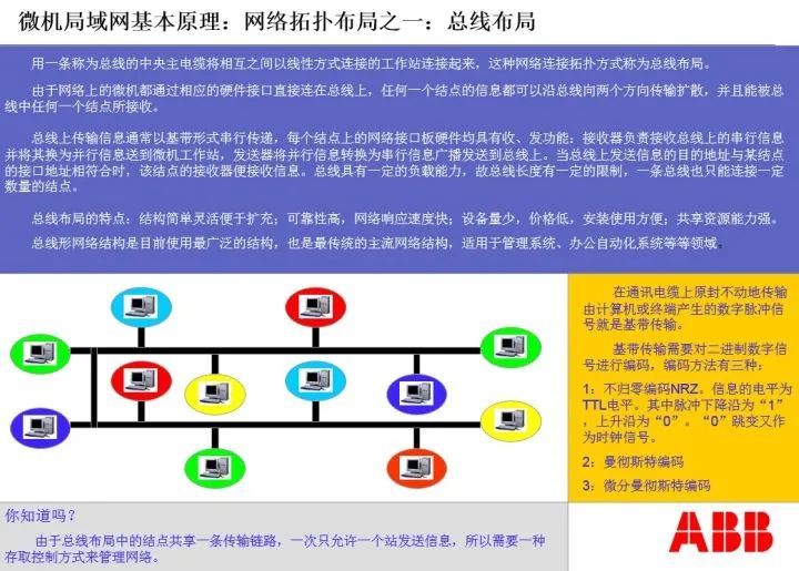
From an electrical wiring perspective, the links are parallel. However, from a communication perspective, the links are daisy chained, representing a sequential and orderly connection.
Now we can summarize:
The RS485 bus network wiring method must be a daisy chaining method and is a half duplex communication method; RS232 is a point-to-point wiring method and is a full duplex communication method. Whether it is the RS232 interface or the RS485 interface, they must comply with the communication regulations of the physical layer.
Next, let’s look at the MODBUS-RTU communication protocol:
Having a physical layer communication interface does not guarantee communication. The answer is no. The physical layer communication interface only enables communication conditions for both parties. However, if neither party understands what the other is saying, or if their speaking methods and grammatical structures do not match, communication cannot occur.
In the OSI model, above the physical layer is the data link layer. The MODBUS-RTU protocol is a data link layer protocol, and as long as both parties use the MODBUS-RTU protocol, it ensures that the communication language is in a format both can understand.
Note the term “statement” here. The physical layer defines bytes, which are akin to words in a language, while the data link layer organizes bytes into statements, or frames. Frames specify the grammatical structure of the statements used by both communication parties.
MODBUS is also master-slave based. Similar to the bus control in the physical layer, the master-slave relationship here regulates control rights over the communication bus. The master station first issues a command, occupying the bus; then it vacates the bus for the slave to write the response code; once the slave completes its task, it returns the bus to the master station.
Now let’s look at the frame structure defined by ISO’s HDLC, which is the grammatical structure of communication statements, as follows:

Under the MODBUS communication protocol, different command function codes have varying frame structures. For the read register command, the frame structure for the MODBUS master is: 2 bytes of address code, 1 byte of function code, 2 bytes of data address code, and 2 bytes of CRC check code; the frame structure for the MODBUS slave response is: 2 bytes of function code, 1 byte of total response byte count, N bytes of response data, and 2 bytes of CRC check code.
Although the physical layer protocol and data link layer protocol differ, the execution of the data link layer protocol must be based on the requirement that the physical layer connection between both communication parties meets the standards and allows for unobstructed information exchange.
This rule must be thoroughly executed in the seven-layer protocol of the ISO/OSI model. In the ISO/OSI model, the lower-level protocols of both communication parties must establish a transparent, fault-free connection and information exchange relationship for the upper-level protocols. In other words, the hierarchical relationships between layers must be absolute.
From the data link layer upwards, we reach the network layer. Its task is to form the information exchange network of the fieldbus.
The functions of the network layer include: packaging communication frames into data packets and then sending the data packets to the other party.
Since the network structures of the two communication parties may differ, the same networks need to be connected via bridges, while different networks require gateways.
There may be multiple channels between networks. When sending data packets, there are various paths to choose from. The component responsible for path selection is called a router. Routers not only determine the actual path of data exchange networks but can also construct virtual network paths and decide the order of sending data packets. Therefore, routers are the most complex and critical equipment in the network layer.
In the OSI model, the physical layer + data link layer + network layer is collectively referred to as the fieldbus, with an 8-pin RJ45 crystal head as the communication interface. Clearly, RJ45 is entirely different from RS232/RS485/RS422.
The data packets at the network layer are combinations of data frames. In layman’s terms, a data packet is a short article or a unit of data to be transmitted.
When sending data packets, the routing and reception combination issues at the network layer are illustrated below:
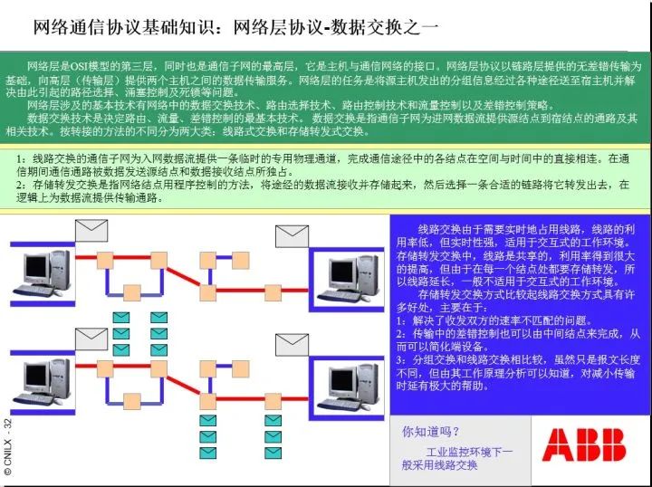
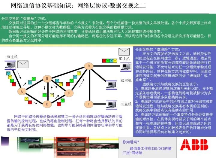
We see that at the network layer, the router first determines the routing path, then sends the packet to the other party. Upon receiving the packet, the other party combines the packets in order and unpacks them into the actual document.
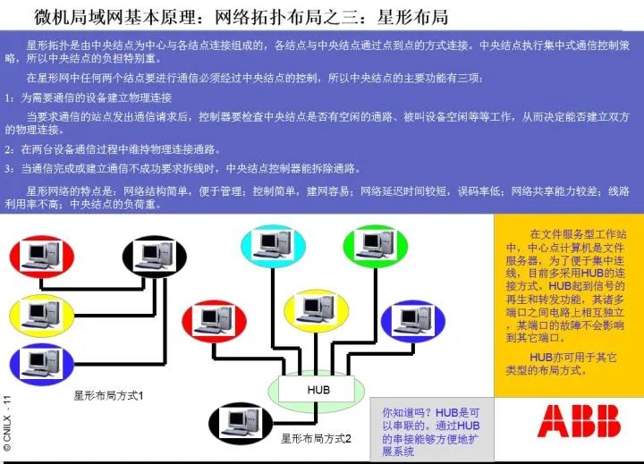
It is noteworthy that with the presence of routers at the network layer, star network structures are supported.
Now let’s focus on the ISO/OSI seven-layer model, as follows:
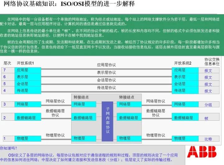
It is essential to clarify that from the network layer upwards, the information units sent between layers are complete messages. The OSI model also specifies the grammatical structure of messages, which will be omitted for brevity.
It is important to note that the definitions of RS232/RS485/RS422 communication interfaces are very clear, including pin levels, functional definitions of pins, and the timing relationships of data flow during information sending and receiving, all of which must be precise and strict; otherwise, information exchange cannot be executed.
When a PLC exchanges information with an electrical instrument that complies with RS485/MODBUS-RTU communication specifications, what do we need to do?
First, we wire according to the daisy chaining communication link requirements, connecting the PLC’s communication interface with N electrical instrument interfaces. A 100-ohm termination resistor must be added at the end of the last electrical instrument.
Second, we assign addresses to these N electrical instruments based on the principle of incremental addressing, such as 01H, 02H, 1FH, etc. Here, H indicates hexadecimal, and 1F represents 16 + 15 = 31.
Third, we set the specified communication rate for the electrical instruments in the PLC programming software.
Fourth, we configure the MODBUS communication code and the cyclic relationship of each slave station in the PLC programming software according to the data area address code of the electrical instruments.
Note: The MODBUS communication code here meets the IEC 61131-3 programming module requirements of the PLC; general PLC ladder diagrams do not have this function. Ladder diagrams meet the IEC 61131-1 requirements but do not meet the IEC 61131-3 requirements.
Fifth, we allocate a dedicated data area in the PLC memory to store the information read from the electrical instruments after processing, so that higher-level master stations can read this information. This data area is called a data point table, sometimes referred to as a communication protocol.
Finally, of course, we perform a startup test. There is much content involved, which will not be elaborated due to space constraints.
Now, let’s look at an example of reading data using MODBUS-RTU on an RS485 network:
For an electrical instrument with address 01H, three-phase current and voltage data, totaling six data points, are stored at memory position 2000, with each data point occupying two bytes, making a total of 12 bytes.
The communication rate for this electrical instrument is 9600 bps. What does this mean? Bps indicates bits, meaning that 9600 bits can be sent on this bus per second. We know that one byte consists of 8 data bits, 1 start bit, and 1 parity bit, totaling 10 bits. Therefore, if the communication rate of the electrical instrument is 9600 bps, we can send: 9600/10 = 960 bytes per second.
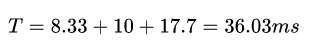
We also know that in the frame structure of the master station’s read data (downstream frame), there is 1 byte for the address, 1 byte for the function code, 2 bytes for the memory address, 2 bytes for the data quantity, and 2 bytes for the CRC check code, totaling 8 bytes. Thus, the time taken for the master station to send the read data MODBUS communication frame is: 8X10/9600 = 8.33 milliseconds.
In this case, we know that the MODBUS-RTU read data command is 0X03H, which is the 03 command. Note the format here: 0X is the prefix, 03 is the command, and H indicates hexadecimal.
The specific communication frame is: 01 03 07 D0 00 06 C5 45, where 0X01H is the address, 0X03H is the command, 0X07D0H is the memory address 2000, 0X0006H indicates reading 6 consecutive words, which are the current and voltage parameters in memory, and 0XC545H is the CRC check code for 01 03 07 D0 00 06.
The response frame from the electrical instrument (upstream frame) has a structure of: 1 byte for the address, 1 byte for the function code, 1 byte for the data area byte count, 12 bytes of data, and 2 bytes for the CRC check code, totaling 17 bytes, with a time of: 17X10/9600 = 17.7 milliseconds.
The specific response communication frame from the instrument is: 01 03 0C 00 64 0064 0064 00 DC 00 DC 00 DC D6 F5, where 0X01H and 0X03H have the same meanings as before, 0X0CH indicates that there are 12 bytes in the upload data area, 0X0064H indicates that phase A current is 100A, the following two groups are phase B and C currents, both 100A, and 0X00DCH indicates that phase A voltage is 220V, with the following two groups being phase B and C voltages, both 220V, and finally, 0XD6F5H is the CRC check code.
The master station initiates the downstream communication frame, waits 10 milliseconds for the slave to respond, and then receives the upstream communication frame from the slave, with a total duration of:
If there are 31 identical instruments waiting for the master station to access one by one, the total duration from the master station starting to access the first instrument to the last response is:
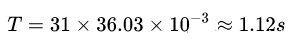
Here, the 1.12 seconds is the read data cycle for these 31 instruments at a communication rate of 9600 bps, and the actual time will be slightly longer, ignoring the waiting time for the master station to send the downstream communication frame again.
We believe that by now, everyone should have a deeper understanding of the communication frames under MODBUS-RTU.
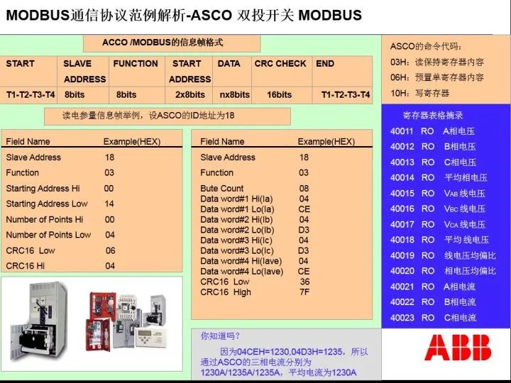
Just a reminder: one word consists of two bytes. Generally, a byte can only express 8 binary states. However, for analog quantities, a word must be used to express them. For example, a current of 1250A is represented in hexadecimal as 04E2H, requiring 2 bytes for a complete expression. Therefore, in various electrical instruments, analog quantities are represented using words.
Below are some commonly used function codes for MODBUS, which are command codes:

Below is an example of the downlink and uplink communication frames when the PLC reads the data point table of the ASCO dual switch controller: