Detailed Explanation of UART Protocol Based on Z20k11X

Detailed Explanation of UART Protocol Based on Z20k11X

Click the blue words

Follow us

1. Introduction

1. Concept
USART (Universal Synchronous Asynchronous Receiver Transmitter) is a serial communication device that can flexibly perform full-duplex information exchange with external devices.
UART (Universal Asynchronous Receiver/Transmitter) is a bidirectional, serial, asynchronous communication bus that can achieve full-duplex communication using only one data receiving line (RXD) and one data sending line (TXD).
The two are similar; UART is trimmed from USART by removing the synchronous communication function and retaining only the asynchronous communication function. The serial communication we usually use is UART.
2. Structure
Any UART bidirectional communication requires at least three pins: data sending pin TXD, data receiving pin RXD, and data reference ground GND. It is particularly important to note the connection method; the signals of device A and device B need to be cross-connected. If the levels are different, a level-shifting chip is needed.
Detailed Explanation of UART Protocol Based on Z20k11X
ARM chips and PC levels differ, so a level-shifting chip like RS232 is required.
Detailed Explanation of UART Protocol Based on Z20k11X
Here, we explain the level standards; depending on the level standards used, they can be divided into TTL and RS232 standards, as shown in the figure:
Detailed Explanation of UART Protocol Based on Z20k11X
Since controllers generally use TTL standards, if RS232 communication is needed, a RS232 converter must be used to convert between TTL and RS232 levels.
3. Characteristics
① When idle, RXD and TXD default to high level.
② The data start bit is low level, with low bit first and high bit last; serial data is generally 8 bits.
③ The serial port can choose whether to enable data verification; the verification bit checks the count of high and low level data in a single byte, commonly using parity.
4. Advantages and Disadvantages
Advantages:
  • Simple: Easy to implement with minimal hardware requirements.
  • No clock signal: No need for clock synchronization between devices.
  • Widely supported: Extensively supported by microcontrollers and peripheral devices.
Disadvantages:
  • Distance limitation: Suitable for short-distance communication; long distances are affected by noise and signal attenuation.
  • Speed limitation: Data transmission rate is lower compared to synchronous communication protocols like SPI or I2C.
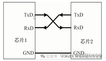
  • Single device communication: Primarily designed for point-to-point communication; additional circuits are needed for multi-device communication.

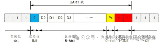
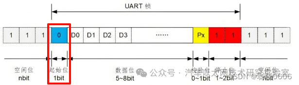
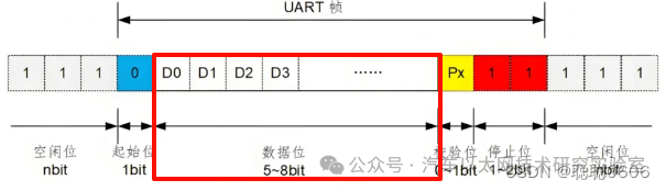
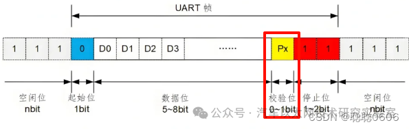
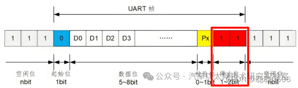
2. Protocol Frame Composition

In UART, the transmission mode is in packet form. A packet consists of a start bit, data frame, parity bit, and stop bit.
Detailed Explanation of UART Protocol Based on Z20k11X
1. Start Bit
Indicates the beginning of data transmission. The receiver identifies the start of transmission by detecting a logic low level. When no data is transmitted, it remains at high level (1); when data transmission starts, it changes to low level (0).
Detailed Explanation of UART Protocol Based on Z20k11X
2. Data Bits
The actual data being transmitted. The length of the data bits can be set during negotiation between the two communicating parties, typically ranging from 5 to 9 bits (commonly 8 bits). When no parity bit is used, it is 9 bits.
Detailed Explanation of UART Protocol Based on Z20k11X
3. Parity Bit
Used for error detection. Common parity methods include Even Parity and Odd Parity. In Even Parity, the number of 1s in the data frame is even; in Odd Parity, the number of 1s is odd. If Odd Parity is used and the total number of 1s in the data frame is even, or if Even Parity is used and the total is odd, UART considers that the bits in the data frame have changed. If no parity bit is used, this part can be omitted.
Detailed Explanation of UART Protocol Based on Z20k11X
4. Stop Bit
Indicates the end of data transmission and is used for receiver synchronization and reset. The stop bit provides a period for the receiver to prepare for the next frame of data. The sending UART drives the data transmission line from low voltage to high voltage and holds it for 1 to 2 bit times.
Detailed Explanation of UART Protocol Based on Z20k11X
Example:
Assuming 8 bits of data are sent, with no parity bit and 1 stop bit, the data is 0x55 (binary 01010101), the UART frame structure is as follows:
| Start Bit | Data Bits | Stop Bit |
| 0 | 01010101 | 1 |

3. UART Communication Process

Sender:
  • The sender begins by sending the start bit.
  • Immediately follows the data bits (from LSB to MSB).
  • If parity is enabled, send the parity bit.
  • Finally, send the stop bit.
Receiver:
  • The receiver starts data reception by detecting the start bit (logic low).
  • Receives data bits sequentially according to the preset baud rate.
  • Checks the parity bit (if any) for error detection.
  • After detecting the stop bit (logic high), completes the reception of one data frame.

4. Difference Between USART and UART

UART
USART
Configuration and Use
Only configure baud rate, data bits, parity bits, and stop bits; suitable for simple point-to-point communication.
In addition to the same configuration as UART, it also requires configuring clock settings for synchronous mode, suitable for high-precision, high-speed communication scenarios.
Data Transmission
For example, at 9600 baud rate, 9600 bits can be transmitted per second.
In synchronous mode, higher data transmission rates can be achieved through higher clock frequencies.
Example:
UART data transmission:
  • Sender: Data 0x55 (binary 01010101), baud rate 9600, no parity bit, 1 stop bit.
  • Receiver: After detecting the start bit, reads the data bits according to the configured baud rate, checks (if any), and then waits for the stop bit.
USART data transmission (synchronous mode):
  • Sender and receiver share a clock signal.
  • Sender: Data 0x55 (binary 01010101), clock frequency of 1MHz.
  • Receiver: Reads data bits according to clock frequency, achieving higher transmission rates.

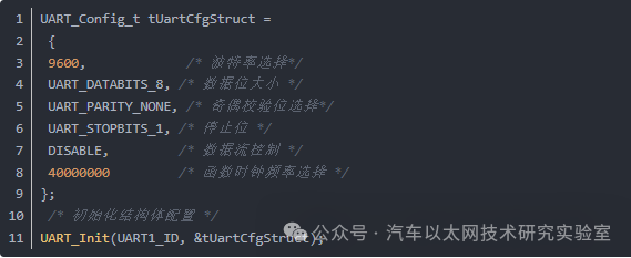
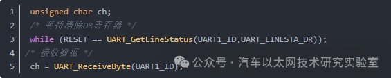
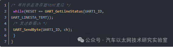
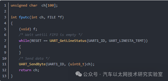
5. Code Implementation

The effect of this experiment is to redefine the printf function to output Hello world!
1. Hardware Block Diagram
Detailed Explanation of UART Protocol Based on Z20k11X
2. Software Implementation
① Initialize structure
Detailed Explanation of UART Protocol Based on Z20k11X
② Serial port receiving function
Detailed Explanation of UART Protocol Based on Z20k11X
③ Serial port sending function
Detailed Explanation of UART Protocol Based on Z20k11X
④ Redefine printf
Detailed Explanation of UART Protocol Based on Z20k11X
The code briefly introduces the functions for sending and receiving serial ports as well as redirecting printf for printing. The code is simple, so the complete code is not included.

Detailed Explanation of UART Protocol Based on Z20k11X

Detailed Explanation of UART Protocol Based on Z20k11XDetailed Explanation of UART Protocol Based on Z20k11X

Source: Congcong0606
*Disclaimer: This article is original or forwarded by the author.If it inadvertently infringes on any party’s intellectual property rights, please inform us for deletion. The above images and text are sourced from the internet; if there is any infringement, please contact us in a timely manner, and we will delete it within 24 hours. The content of the article represents the author’s personal views,The Automotive Ethernet Technology Research Laboratory reprints it only to convey a different viewpoint and does not representThe Automotive Ethernet Technology Research Laboratory‘s agreement or support for this viewpoint. If there are any objections, please feel free to contact the Automotive Ethernet Technology Research Laboratory.
Original link:
https://blog.csdn.net/2201_75342985/article/details/139855314

Leave a Comment