
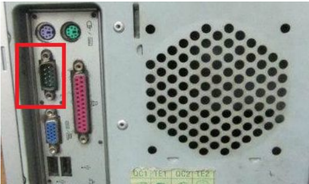
Before discussing RS485 communication, it is necessary to mention RS232 communication. If you are not familiar with RS232 communication, don’t worry. You have definitely seen and used the RS232 interface (if you don’t believe it, you can check behind your desktop computer at home).
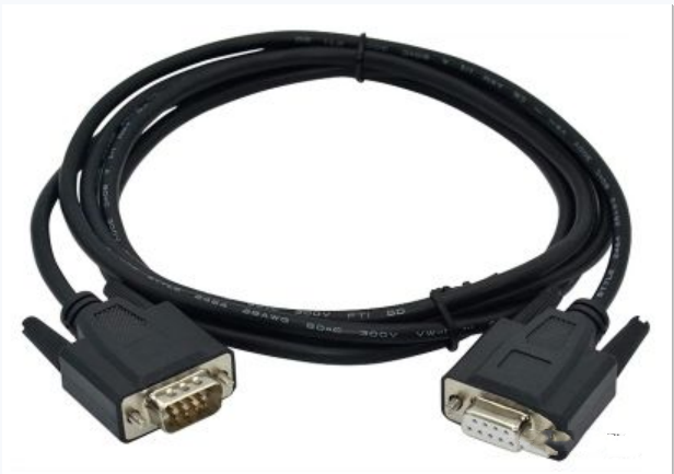
In fact, many people use the Siemens PCPPI programming cable to achieve the conversion between RS232 and RS485 communication when programming the S7-200 series PLCs. Here, “PC” can be understood as the RS232 interface connected to a computer, and “PPI” can be understood as the RS485 interface connected to the PLC. “PPI” is a protocol that uses RS485 as the medium (physical layer).
Why Choose RS485 Communication
For example, since RS232 communication can only be used for point-to-point communication, such as from a computer to a PLC, if the number of nodes that need to communicate in the system exceeds two, it cannot directly meet the requirement. Therefore, the EIA (Electronic Industries Alliance) established a new interface standard, RS485, which supports point-to-multipoint communication.
The electrical standard for RS485 communication is the RS422 (Mitsubishi PLC programming port) communication standard. RS485 is a variant of RS422A. RS422A is full duplex, using two pairs of balanced differential signal lines for transmission and reception. RS485 is half duplex, using only one pair of balanced differential signal lines, meaning it cannot send and receive simultaneously.
Key Point: RS485 is half duplex and has master-slave communication.
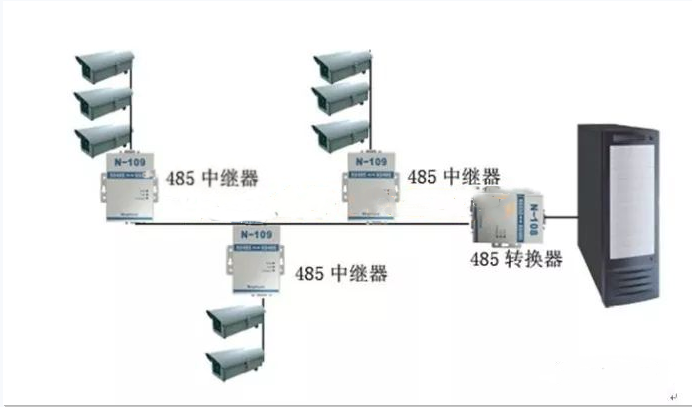
The RS485 communication interface and twisted pair can be used to form a serial communication network, which will be mainly discussed below, to form a distributed system with up to 32 stations. If the number of devices connected in the network exceeds 32, RS485 repeaters can be used, allowing connections to up to 128 stations.
Focus: RS485 supports multi-station and multi-device communication.
RS485 Communication Wiring
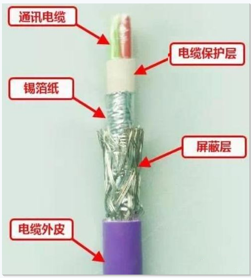
To effectively suppress interference, shielded twisted pair cables are typically used as the communication medium, such as Siemens’ Profibus DP cable:
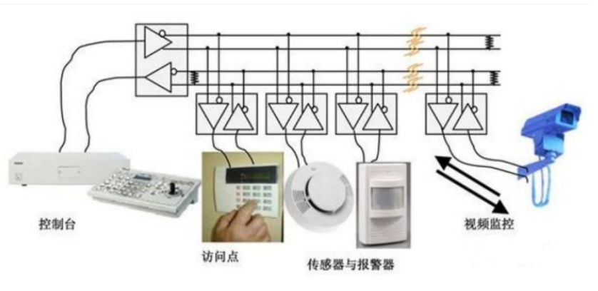
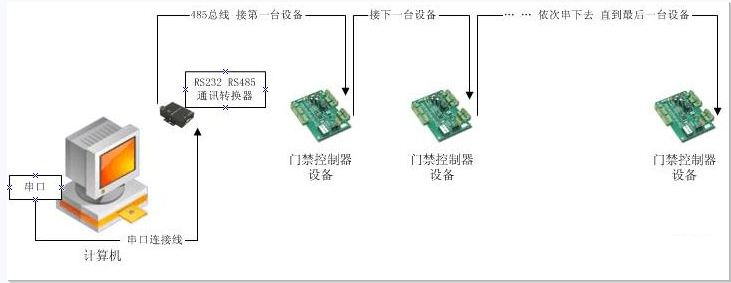
The wiring for RS485 communication for each device is very simple. The prerequisite is to ensure that each device is connected in a “daisy chain” (it requires a lot of wires or cables, and if there are many devices, it is easy to use hubs or repeaters, as described below). To avoid communication failures and reduce interference, do not have star connections or branches.
You might ask how the devices in the diagram are directly connected in a “daisy chain”. Please look at this:
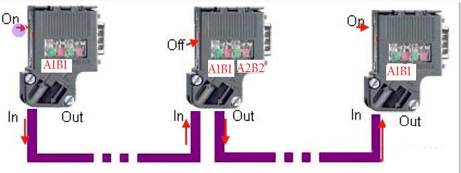
Siemens has a cable connector specifically designed for RS485 communication (Profibus DP connector/plugs). This connector also has terminal resistance and is easy to use. It is quite expensive, over 100 for the original, but domestic ones are also compatible (affordable); some devices are wired in the form of terminals when connecting RS485 communication, and the wiring method can refer to the cable connector’s connection method.
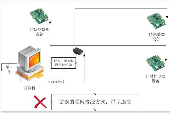
Below are two incorrect connections:
RS485 Communication Bus Wiring
In simple applications of RS485 communication, bus topology is typically used. However, in more complex systems, the wiring structure of bus topology is not only very cumbersome but also wastes a lot of connections. Flexibly using 485 hubs or 485 repeaters can connect the bus topology into star or tree topology, greatly facilitating early construction and later maintenance work.
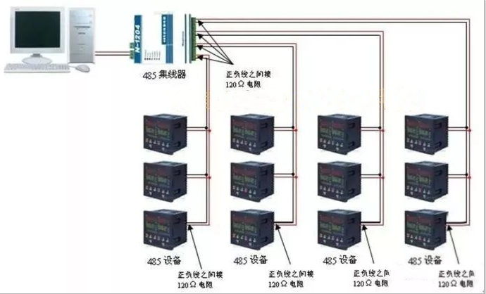
485 Bus Star Topology
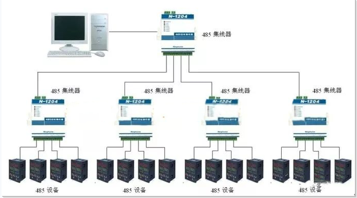
485 Bus Tree Topology
Connecting Terminal Resistance
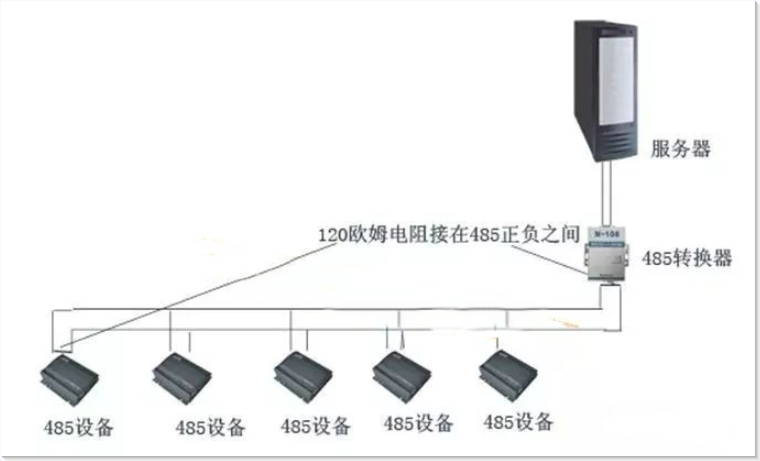
In the actual application of the 485 bus, when the transmission distance exceeds a certain length, the anti-interference capability of the bus decreases. In this case, it is necessary to connect a 120-ohm terminal matching resistor at both ends of the 485 bus to ensure the stability of the 485 bus.
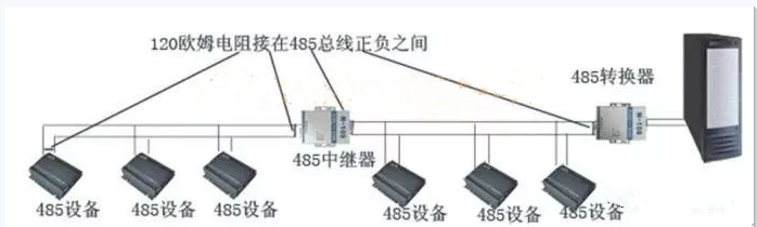
The correct connection method for the terminal matching resistor is to connect a 120-ohm terminal resistor between the positive and negative lines of the 485 bus at the outlet of the device at the head end of the 485 bus and the inlet of the terminal device, as shown below:
Using a 232 to 485 converter alone
When adding a 485 repeater
When using a 485 hub
Some Misunderstandings and Additions about RS485 Communication
I remember a student called me on site, saying that his PLC could not read data from the flow meter. After verification, the program and hardware connections were fine, and the computer was tested with serial port debugging software, but it could not read the instrument data.
My first question was: What communication protocol do your PLC and instrument use?
He was silent for a moment and then said: The communication between the PLC and the instrument is not based on the RS485 communication protocol. This is the RS485 communication protocol!
His answer may satisfy the wishes of many friends. The term RS485 communication protocol sounds harmonious, but in fact, they are not suitable because a protocol is a protocol, and RS485 communication is a medium (physical layer), and this should not be confused.
For example, when making a phone call, the phone is the physical layer, and the language between callers is the protocol. The same physical layer can transmit different protocols, just as people on either side of a mobile phone can communicate in different languages (protocols). RS485 communication is like a phone, capable of transmitting PPI protocol, MODBUS protocol, PROFIBUS protocol, etc.
After more than an hour of communication, it was learned that there was a frequency converter around the instrument, and the power line and communication line were intertwined. Therefore, the power line and signal line were wired at a certain distance, and terminal resistance was added at the outlet and end of the communication line.
The reason he did not add terminal resistance was that he thought the distance between the instrument and PLC was relatively short (a few meters to a dozen meters), which is actually a misunderstanding because distance is not the issue; the main issue is signal interference. Of course, some communication ports have been isolated, so there is no need to add it at this time!
Finally, the results of the communication with the trainee were speculated~
Regarding the choice of terminal resistance value:
I personally believe that the size of the terminal resistance is related to the device interface and cable, and there is also a special calculation formula. Frankly, it is actually a range of values. In my personal practice, I have never reached 120! The farther the distance, the more apparent the effect. Therefore, to ensure communication quality, it is best to add!