This article introduces the implementation process of an Automated Guided Vehicle (AGV) control system, divided into hardware setup and software design.
1.1 Types of On-Board Controllers
The on-board controller is the core of the control system and the entire AGV. So which controller should be chosen? Based on the author’s experience, from a hardware perspective, the on-board controllers used in AGVs can be roughly divided into three categories:
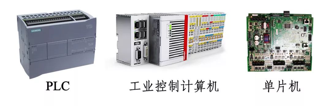
1) PLC: Representative products include Siemens’ S7-1200 and 1500 series, used by AGV manufacturers such as Jiasun and Jiateng. PLCs are known for their stability and reliability, but their strong suit is logical control, and they can generally only perform simple motion control. The price of Siemens PLCs ranges from about 2000 to 12000 yuan.
2) Industrial Computer: Representative products include Beckhoff’s CX5130, used by manufacturers such as Kunshan and Robert. An industrial computer is essentially a computer, but it is designed to have strong anti-interference capabilities, suitable for harsh industrial environments such as vibration and electromagnetic radiation. Industrial computers are compact and can run general operating systems like Windows and Linux. For instance, after installing Beckhoff’s TwinCAT control software, it inserts a real-time kernel into the Windows operating system, turning the computer into a real-time control system suitable for industrial applications. The price of Beckhoff industrial computers ranges from about 5000 to 30000 yuan.
3) Microcontroller: Representative products include STM32, used by manufacturers such as Haitong and Jike. Compared to the first two, microcontrollers are cheaper, and the cost of peripheral components is generally less than a thousand yuan. One drawback of using microcontrollers is that if you want to create a mature product, you need to spend a lot of effort designing external circuits and various low-level algorithms. The software development environment may also be less favorable.
The above classification does not mean that the three are completely distinct. For example, the core chip of a PLC may be a microcontroller; the programming languages used in industrial computers may include ladder diagrams and ST languages commonly used in PLCs; microcontrollers can also run operating systems, forming a complete controller. Therefore, while each has its applicable fields, they also complement each other, evolving into a situation where each contains elements of the others.
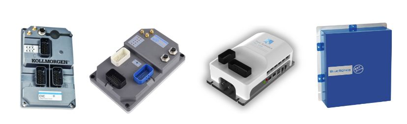
Of course, there are now dedicated AGV controllers on the market, such as the CVC600 from the US NDC, ANT from Switzerland’s BlueBotics, MRC5000 from Zhejiang Kecong Intelligent, and SRC from Shanghai Xianzhi Robot. Compared to general industrial motion controllers or PLCs, these dedicated controllers integrate mature navigation and motion control algorithms, saving users a lot of work, and they also have higher stability and protection levels, but their prices are also higher (20,000 to 60,000 yuan).
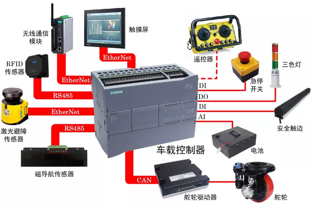
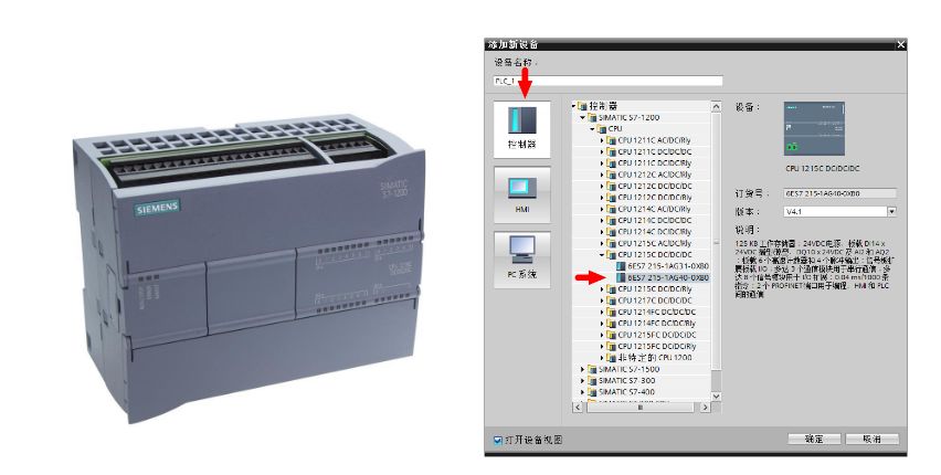
I chose the Siemens S7-1215C PLC as the on-board controller for the AGV (hereinafter referred to as S1200), as shown in the figure below. Due to the wide variety of Siemens product models, each model has slight differences in interface types, performance, etc. When purchasing, it is best to use the order number to accurately describe which model it is. Each Siemens product has a unique order number, and you only need to provide this number during procurement. You can also find the corresponding model in Siemens’ programming software according to the order number. However, there are some disadvantages to using Siemens products. For example, their PLCs are general products, not specifically designed for vehicle control. A 100 yuan ARM development board on Taobao has RS485, CAN, and Ethernet interfaces, while Siemens requires a high price for this. The openness of Siemens products is very poor. Therefore, future AGVs will gradually phase out Siemens products.
What are the Host and Slave Machines?
Some devices can access other devices, such as reading data from memory and writing data to memory. Such devices have higher permissions and status, hence are called host machines. Some devices can only be accessed by other devices and do not have the authority to access other devices, which are called slave machines. In this article, the PLC is the slave machine, while the programming computer is its host machine.
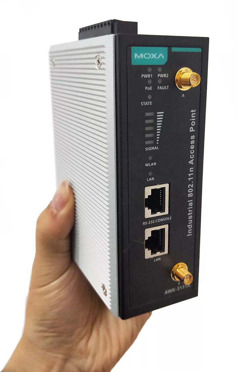
To set or program the PLC, you need to connect the S1200 to the host machine using a network cable. You only need to set the IP address of the host machine to be in the same subnet as the PLC. The default IP address of the S1200 is generally 192.168.0.1, so you can set your computer’s IP to 192.168.0.2. For mobile devices like AGVs, wireless communication is usually adopted, such as receiving control commands from the dispatching system. Wireless communication methods include WIFI, ZigBee, etc. Since WIFI is commonly used in practice, I will introduce its configuration method. Connecting Siemens PLC via WIFI is very convenient. You only need to connect the PLC’s Ethernet port to the LAN port of the wireless router using a network cable, and then connect to the PLC by searching for the corresponding WIFI on your laptop. The wireless router can be of any brand, even a home router. (The author once bought a domestic Ethernet to WIFI converter on Taobao, but strangely it did not support the TIA Portal software (the TIA Portal could not access the PLC), so it’s best to confirm with the seller before purchasing whether it can be used with TIA Portal. If you want more stable and reliable communication, you can choose industrial-grade communication modules, such as MOXA, which is compatible with a power supply voltage of 12V~48V.)

Driver
If the on-board controller is the brain of the AGV, then the AGV also needs a heart and muscles to move. The driver provides current to the motor of the wheels, equivalent to the heart.
2.1 Low Voltage Driver Brands
Since AGVs generally use batteries for power, their voltage is typically around 12V to 72V. Therefore, the drivers used by AGVs belong to low-voltage DC servo drivers. Foreign low-voltage driver brands include: AMC, RoboteQ, ZAPI, Curtis, Elmo, etc. Domestic low-voltage driver brands include: Buke, Senchuang, Yingboer, Kelly.
2.2 Communication Between PLC and Driver
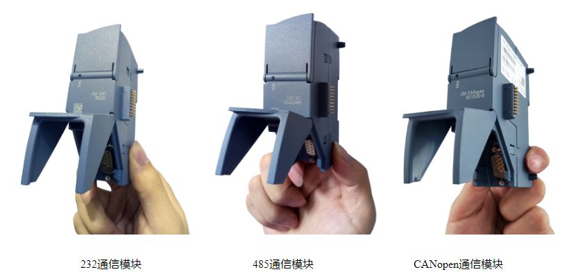
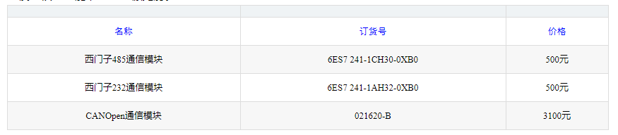
For the PLC to control the driver, it must send command data to it. Low-end drivers can use analog signals or pulse signals to transmit data, while high-end drivers use standardized communication protocols. This communication can be achieved using protocols such as RS-232, RS-485, CAN, EtherCAT, etc. Since the CPU module of the S1200 does not have these communication interfaces, to connect the driver, an additional communication module (CM: Communication Module) must be purchased. Siemens has corresponding communication modules for the mentioned protocols, such as Siemens’ RS-232, RS-485, and CANopen communication modules as shown in the figure below (these three modules look exactly the same). Note that the RS-232 and CANopen modules have male connectors, while the RS-485 has a female connector.
For mobile devices, the CAN bus is the most commonly used communication method. Vehicles, excavators, and AGVs generally use CAN bus communication. The CAN bus is fast (up to 1Mb/s, faster than RS-485), highly stable (uses differential signals, resistant to interference), and more intelligent (has priority and arbitration mechanisms). Therefore, CAN bus should be prioritized. However, considering that Siemens does not have a CAN communication module (if you want to use CAN, you need to purchase a CANopen module from a third-party company like HMS), this article uses the RS-485 protocol for the driver, so we choose the RS-485 module.
Another question that arises is: How many communication modules can the S1200 expand? The answer is: 3. Regardless of the type of communication module, the maximum number is 3, and the types can be mixed. If your driver is bus-type (both RS-485 and CAN are bus-type), then only one RS-485 module or CANopen module is needed. Note that RS-232 is not bus-type, so if you use two drivers, you will need to add two communication modules. If your AGV has other sensors using different communication protocols (such as magnetic navigation sensors, RFID sensors), then 3 communication modules may become insufficient.
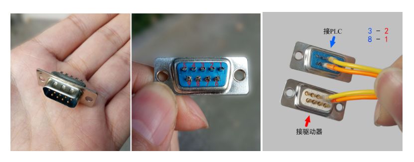
Siemens’ RS-485 module uses a standard 9-pin D-sub connector. To connect the driver and PLC, we need to purchase a DB9 connector and connect the two ends with signal wires. Here we only need to use two signal wires. It is worth noting that Siemens’ RS-485 interface definition is different from conventional RS-485. In conventional RS-485, the signal transmission uses pins 1 and 2, while Siemens’ RS-485 uses pins 3 and 8 (refer to page 1769 of the manual). Therefore, when wiring, solder according to the corresponding order of 3-2 and 8-1, as shown in the figure below.
For AGVs to achieve transportation and transfer, they need a mobile mechanism. The commonly used mobile mechanisms include steering wheels, differential wheels, and Mecanum wheels. What are the characteristics of each, and in what situations should each type of wheel be used?
The advantage of Mecanum wheels is high motion accuracy, but they have a complex structure, severe wear, and are picky about the ground. Although Mecanum wheels have been around for over 30 years, their actual application is still not widespread, indicating that they are not a practical product. Below, we mainly explain steering wheels.
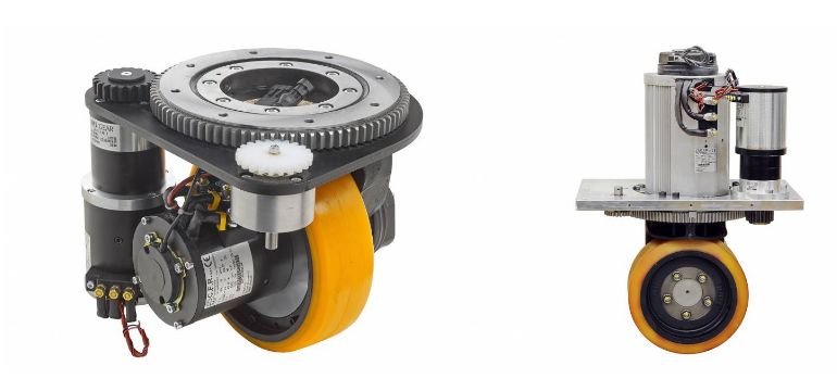
The steering wheel is a highly integrated mobile mechanism composed of wheels, rotary supports, gearboxes, drive motors, steering motors, encoders, limit switches, and brakes. It can provide traction and actively steer, so a steering wheel has two degrees of freedom. An AGV can achieve omnidirectional movement using one or more steering wheels: rotating in place, diagonal movement, lateral movement, etc. Steering wheels are generally used in indoor environments, so the wheel surface material is mostly polyurethane. Depending on the installation position of the motor, steering wheels can be divided into two types: horizontal and vertical, as shown in the two figures below. The horizontal steering wheel has the drive motor installed laterally, resulting in a low overall height, which is suitable for some AGVs that have height requirements (for example, penetrative AGVs that need to be very low to fit under cargo). The vertical steering wheel has the drive motor installed vertically, resulting in a higher overall height. Its advantage is that it is convenient to isolate the motor, which is suitable for some situations (such as hazardous materials factories) where the steering wheel motor needs to be isolated from the external environment. Major foreign steering wheel manufacturers include Italy’s CFR and Germany’s Schabmuller. Later, a manufacturer called Maluda was independently established from CFR. These steering wheel manufacturers generally only sell steering wheels and do not provide drivers, which are provided by agents. The most expensive component on an AGV is the steering wheel. For an AGV costing around 100,000 yuan, if equipped with two steering wheels, it can cost 40,000 to 50,000 yuan, accounting for nearly half of the total vehicle cost. However, the good news is that domestic steering wheel manufacturers are starting to compete, which will reduce AGV costs.
 Magnetic Navigation Sensors and Magnetic Strips
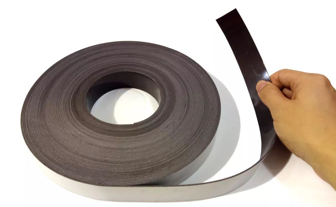
Magnetic strip navigation is currently one of the most used navigation methods for AGVs. You only need to lay magnetic strips on the ground in advance, and the AGV will move along the path formed by the magnetic strips. Magnetic strips are generally 3-5 cm wide, resembling tape, with one smooth side and one sticky side, which can be adhered to the ground to complete the laying. Magnetic strips have polarity, so pay attention to whether it is N-pole or S-pole when purchasing. The polarity of the magnetic strip corresponds to the polarity of the magnetic navigation sensor, but some sensors are compatible with both. Magnetic strips are soft and not pressure-resistant, so if they are repeatedly crushed by wheels, they may become flattened or fall off. Most AGVs avoid damaging the magnetic strip by arranging the drive wheels on the sides of the vehicle (differential form) or in a diagonal symmetrical position.
Magnetic Navigation Sensors and Magnetic Strips
Magnetic strip navigation is currently one of the most used navigation methods for AGVs. You only need to lay magnetic strips on the ground in advance, and the AGV will move along the path formed by the magnetic strips. Magnetic strips are generally 3-5 cm wide, resembling tape, with one smooth side and one sticky side, which can be adhered to the ground to complete the laying. Magnetic strips have polarity, so pay attention to whether it is N-pole or S-pole when purchasing. The polarity of the magnetic strip corresponds to the polarity of the magnetic navigation sensor, but some sensors are compatible with both. Magnetic strips are soft and not pressure-resistant, so if they are repeatedly crushed by wheels, they may become flattened or fall off. Most AGVs avoid damaging the magnetic strip by arranging the drive wheels on the sides of the vehicle (differential form) or in a diagonal symmetrical position.
4.2 Magnetic Navigation
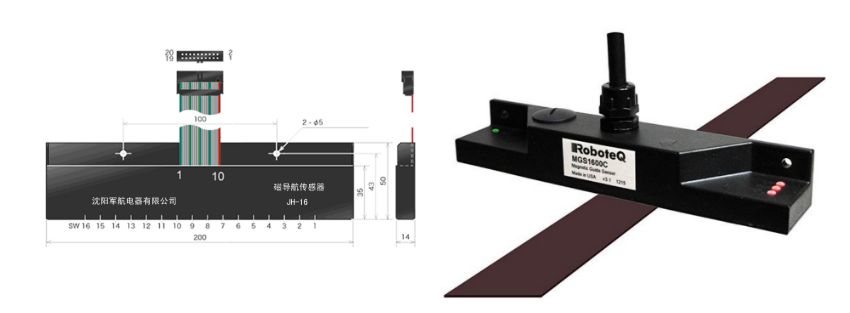
Magnetic navigation sensors, also known as magnetic line-following sensors, help AGVs walk along the line. Magnetic navigation sensors are generally installed on the AGV body or the drive wheel group, and they maintain a certain height above the magnetic strip while the AGV is in motion. The installation position of the magnetic navigation sensor relative to the body is generally on the symmetrical central axis, typically symmetrically installed, such as one in the front and one in the back or one on the left and one on the right. The principle of the magnetic navigation sensor is simple: there are several probes on the sensor, each capable of detecting the magnetic field. Probes located above the magnetic strip (within a certain height) have signal outputs, while probes that exceed the magnetic strip do not. The more probes, the higher the resolution of the sensor, of course, the higher the price. Common sensor point counts include 6 points, 8 points, and 16 points. Magnetic navigation sensors are not mysterious devices; the author has previously disassembled a magnetic navigation sensor, and the probes mentioned are essentially two types: Hall elements and geomagnetic sensors. Hall elements can sense magnetic fields, are low-cost, but usually have low accuracy; geomagnetic sensors generally use products from PNI in the USA.
It needs to be paired with a dedicated driver chip, PNI-12927, which operates at 3.3V, so the sensor must have a 3.3V voltage regulation circuit designed internally, and this driver chip uses an SPI bus, which requires signal processing and voltage conversion, typically handled by a microcontroller. The output signal of the magnetic navigation sensor can be either digital or bus-type data. For sensors with many points, bus-type is generally used, as using digital signals would require many wires. For example, if an AGV uses 4 sensors, each with a resolution of 16 points, that would require 4×16=64 outputs, and the corresponding PLC should have 64 digital input ports, making the wiring very cumbersome and prone to failure (for example, if a wire connection is loose).
Magnetic navigation is simple to implement and inexpensive, but it also has many drawbacks, one serious problem being interference. During the debugging of the AGV, the author found that even when the sensor was not above the magnetic strip (sometimes even when there were no magnetic strips nearby), the sensor still had outputs. After some thought, the author discovered the problem. There was a railway track in front of the AGV, and iron is easily magnetized. Not only iron products but also energized wires can cause the sensor to misreport. Therefore, when using magnetic strip navigation, it is essential to eliminate these interferences.
The output of the magnetic navigation sensor can be IO or numerical (representing the distance from the center of the magnetic strip). How does the magnetic navigation sensor connect to the PLC? As mentioned above, if the sensor uses a bus (such as RS-485) to transmit data, simply connect the bus to the corresponding (RS-485) communication module. If the sensor uses a digital interface, it must be connected to the digital input port of the PLC. Here is an important question: you need to be clear on whether the sensor output signal is PNP or NPN type, which corresponds to the type of transistor. The difference is that when there is a signal, the PNP outputs a high level (e.g., 24V), while the NPN outputs a low level (e.g., 0V). On the S1200, there is a COM port next to each input/output port, which is used to select whether the input is PNP or NPN. If it is PNP, the COM port should be connected to 24V; if it is NPN, it should be connected to 0V. You can test a magnetic strip with a multimeter; if it shows 24V when placed on the magnetic strip, it indicates it is PNP type. You will find that many sensors are divided into PNP and NPN types, and their wiring is the same.
 The AGV requires a large current at startup, so it needs to use a power battery. The most commonly used power batteries are lead-acid batteries and lithium batteries. Lead-acid batteries have a short lifespan and low energy density, while lithium batteries have high density but are also expensive. There is another type of battery called supercapacitors, which have a long lifespan but very low energy density, so they are not widely used.
Well-known battery manufacturers include Hawker and Hoppecke. The following is a label of a Hawker AGV-specific battery. The rated discharge current of lead-acid batteries is generally 0.5C, for example, an 80Ah battery has a rated discharge current of 0.5×80=40A. The maximum discharge current of lead-acid batteries is generally 3C, i.e., 3×80=240A. The voltage of the battery gradually decreases as the charge is consumed, starting to decrease slowly, and then sharply dropping when the charge is low. Based on this relationship, by detecting the voltage, you can know how much charge is left in the battery and whether it needs to be recharged.
How do we estimate what capacity battery an AGV should choose?
The most power-hungry component on an AGV is the motor. Generally speaking, the rated power P of the motor will be written on the motor nameplate. According to basic physics knowledge, power equals voltage multiplied by current, i.e.,
The rated voltage of the drive motor is generally easy to obtain, so you can calculate the current using the above formula. Of course, the actual working power is generally less than the rated power, so you should multiply by a factor, depending on the AGV’s load, working surface, etc. The current multiplied by the working time gives the battery capacity. Note that battery capacity and energy are two different concepts; the former is current multiplied by time (measured in “amp-hours” (Ah)), while the latter is current multiplied by voltage multiplied by time (measured in “kilowatt-hours” (KWh)).
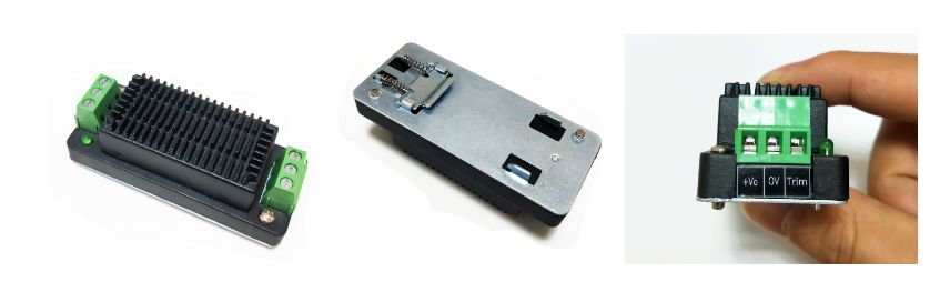
If the voltage output of the battery differs from that of the sensors, controllers, and other devices, a voltage conversion module is needed, which can also serve as a voltage regulator. The common voltages for sensors are 12V, while controllers typically use 24V, so corresponding modules are needed. You can choose voltage conversion modules from Guangzhou Jinshengyang, which can be equipped with heat sinks and rails for better heat dissipation and fixation, such as the 48V to 24V module shown below. When choosing a module, the main concern is the power, that is, the maximum current it can provide.
The AGV requires a large current at startup, so it needs to use a power battery. The most commonly used power batteries are lead-acid batteries and lithium batteries. Lead-acid batteries have a short lifespan and low energy density, while lithium batteries have high density but are also expensive. There is another type of battery called supercapacitors, which have a long lifespan but very low energy density, so they are not widely used.
Well-known battery manufacturers include Hawker and Hoppecke. The following is a label of a Hawker AGV-specific battery. The rated discharge current of lead-acid batteries is generally 0.5C, for example, an 80Ah battery has a rated discharge current of 0.5×80=40A. The maximum discharge current of lead-acid batteries is generally 3C, i.e., 3×80=240A. The voltage of the battery gradually decreases as the charge is consumed, starting to decrease slowly, and then sharply dropping when the charge is low. Based on this relationship, by detecting the voltage, you can know how much charge is left in the battery and whether it needs to be recharged.
How do we estimate what capacity battery an AGV should choose?
The most power-hungry component on an AGV is the motor. Generally speaking, the rated power P of the motor will be written on the motor nameplate. According to basic physics knowledge, power equals voltage multiplied by current, i.e.,
The rated voltage of the drive motor is generally easy to obtain, so you can calculate the current using the above formula. Of course, the actual working power is generally less than the rated power, so you should multiply by a factor, depending on the AGV’s load, working surface, etc. The current multiplied by the working time gives the battery capacity. Note that battery capacity and energy are two different concepts; the former is current multiplied by time (measured in “amp-hours” (Ah)), while the latter is current multiplied by voltage multiplied by time (measured in “kilowatt-hours” (KWh)).
If the voltage output of the battery differs from that of the sensors, controllers, and other devices, a voltage conversion module is needed, which can also serve as a voltage regulator. The common voltages for sensors are 12V, while controllers typically use 24V, so corresponding modules are needed. You can choose voltage conversion modules from Guangzhou Jinshengyang, which can be equipped with heat sinks and rails for better heat dissipation and fixation, such as the 48V to 24V module shown below. When choosing a module, the main concern is the power, that is, the maximum current it can provide.
 When choosing the main power switch, pay attention to whether it is “self-locking” or “automatic reset”. Self-locking means that after pressing it, even if you release your finger, the switch remains closed, allowing power to flow; while an automatic reset switch will cut off the circuit if you release your finger after pressing the button, as shown in the figure below. Generally, the main power switch on the chassis should be selected as self-locking, otherwise you would have to hold the button continuously to keep the circuit flowing, so do not purchase the automatic reset switch shown in the right figure (code: XB2-BA31C, priced around 22 yuan). If you buy the wrong one, don’t worry; you can buy a self-locking module ZB2-BZ21 C, which can be added to the XB2-BA31C switch to turn it into a self-locking switch.
6.2 Emergency Stop Switch
One item that can be found on all AGV bodies is the emergency stop switch. According to the national standard GBT 20721-2006 “General Technical Conditions for Automated Guided Vehicles” in section 4.2.6, “AGVs should be equipped with an emergency stop button, which should be conveniently operable in emergencies. The button should be red, and pressing the emergency stop button should cut off the AGV’s drive power.” In the event of loss of control of the AGV, pressing the emergency stop switch can immediately stop its movement, thereby preventing harm to people. Therefore, the emergency stop switch constitutes the last safety barrier. To ensure reliable use, you can purchase Schneider’s XB2-BS542C. The buttons on emergency stop switches are generally designed to be large for easy pressing, so they are commonly referred to as mushroom heads, which are generally self-locking and need to be twisted to release after being pressed. The only thing to pay attention to when purchasing is its installation diameter, generally choosing 22mm will suffice.
When choosing the main power switch, pay attention to whether it is “self-locking” or “automatic reset”. Self-locking means that after pressing it, even if you release your finger, the switch remains closed, allowing power to flow; while an automatic reset switch will cut off the circuit if you release your finger after pressing the button, as shown in the figure below. Generally, the main power switch on the chassis should be selected as self-locking, otherwise you would have to hold the button continuously to keep the circuit flowing, so do not purchase the automatic reset switch shown in the right figure (code: XB2-BA31C, priced around 22 yuan). If you buy the wrong one, don’t worry; you can buy a self-locking module ZB2-BZ21 C, which can be added to the XB2-BA31C switch to turn it into a self-locking switch.
6.2 Emergency Stop Switch
One item that can be found on all AGV bodies is the emergency stop switch. According to the national standard GBT 20721-2006 “General Technical Conditions for Automated Guided Vehicles” in section 4.2.6, “AGVs should be equipped with an emergency stop button, which should be conveniently operable in emergencies. The button should be red, and pressing the emergency stop button should cut off the AGV’s drive power.” In the event of loss of control of the AGV, pressing the emergency stop switch can immediately stop its movement, thereby preventing harm to people. Therefore, the emergency stop switch constitutes the last safety barrier. To ensure reliable use, you can purchase Schneider’s XB2-BS542C. The buttons on emergency stop switches are generally designed to be large for easy pressing, so they are commonly referred to as mushroom heads, which are generally self-locking and need to be twisted to release after being pressed. The only thing to pay attention to when purchasing is its installation diameter, generally choosing 22mm will suffice.
 AGVs have both high voltage and low voltage, for example, the current required by the steering wheel driver is usually very high, while controllers and some sensors only require very low current. We need to design the circuit reasonably to prevent mutual interference, and more importantly, include low-voltage components. According to the national standard GBT 30029-2013 “Design Principles for Automated Guided Vehicles (AGV)” in section 6.7.7.4, the controller should have over-voltage protection, under-voltage protection, and over-current protection functions.
We need to add the following devices to the circuit:
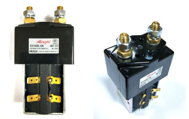
■ �lacksquare■ Contactor: Used to control large currents with small currents. The above power switch only allows small currents to pass, but sometimes some components in the equipment require large currents to start, such as the steering wheel driver. We cannot use one switch to control both small and large currents, so we need to use a contactor. The contactor has an electromagnet inside, and we control the electromagnet’s engagement with a small current, which in turn drives another group of switches to close, allowing large currents to pass. The AGV uses DC contactors, and note that the contactor’s coil will generate some heat, so installation should consider heat dissipation and its effect on nearby components.
Breaker: Acts as over-current and under-voltage protection. A breaker is also like a switch. It disconnects in cases of short circuits or excessive current, protecting the equipment.
Relay: Also acts as a switch, controlled by a small voltage to open and close contacts, but note that the contacts cannot carry too much current.
AGVs use batteries as their energy source, and the voltage of the batteries is usually not very stable; during use, the voltage fluctuates. Although Siemens PLCs have a certain adaptability to input voltage, it is best to use a 24V to 24V voltage regulator module to stabilize the battery voltage before supplying it to the PLC. The same goes for other devices powered by 24V, such as magnetic navigation sensors.
Laser Obstacle Avoidance Sensors
AGV safety protection methods can be divided into contact and non-contact types. Touch edges belong to contact type, while laser sensors and ultrasonic sensors belong to non-contact type. Of course, non-contact sensors are safer because they can monitor obstacles without direct contact.
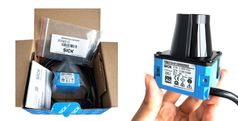
Common foreign laser sensor brands include SICK and HOKUYO. Taking SICK’s Tim310 as an example, it has a detection range of up to 3 meters and can set different monitoring area shapes. The output of Tim310 is I/O signals used to determine whether an obstacle has been detected.
AGVs have both high voltage and low voltage, for example, the current required by the steering wheel driver is usually very high, while controllers and some sensors only require very low current. We need to design the circuit reasonably to prevent mutual interference, and more importantly, include low-voltage components. According to the national standard GBT 30029-2013 “Design Principles for Automated Guided Vehicles (AGV)” in section 6.7.7.4, the controller should have over-voltage protection, under-voltage protection, and over-current protection functions.
We need to add the following devices to the circuit:
■ �lacksquare■ Contactor: Used to control large currents with small currents. The above power switch only allows small currents to pass, but sometimes some components in the equipment require large currents to start, such as the steering wheel driver. We cannot use one switch to control both small and large currents, so we need to use a contactor. The contactor has an electromagnet inside, and we control the electromagnet’s engagement with a small current, which in turn drives another group of switches to close, allowing large currents to pass. The AGV uses DC contactors, and note that the contactor’s coil will generate some heat, so installation should consider heat dissipation and its effect on nearby components.
Breaker: Acts as over-current and under-voltage protection. A breaker is also like a switch. It disconnects in cases of short circuits or excessive current, protecting the equipment.
Relay: Also acts as a switch, controlled by a small voltage to open and close contacts, but note that the contacts cannot carry too much current.
AGVs use batteries as their energy source, and the voltage of the batteries is usually not very stable; during use, the voltage fluctuates. Although Siemens PLCs have a certain adaptability to input voltage, it is best to use a 24V to 24V voltage regulator module to stabilize the battery voltage before supplying it to the PLC. The same goes for other devices powered by 24V, such as magnetic navigation sensors.
Laser Obstacle Avoidance Sensors
AGV safety protection methods can be divided into contact and non-contact types. Touch edges belong to contact type, while laser sensors and ultrasonic sensors belong to non-contact type. Of course, non-contact sensors are safer because they can monitor obstacles without direct contact.
Common foreign laser sensor brands include SICK and HOKUYO. Taking SICK’s Tim310 as an example, it has a detection range of up to 3 meters and can set different monitoring area shapes. The output of Tim310 is I/O signals used to determine whether an obstacle has been detected.
 Nowadays, AGVs are increasingly equipped with touch screens. Using a touch screen allows for easy parameter settings of the AGV, such as motion speed, charging voltage, etc., without needing to download the program to the PLC each time. Since we chose Siemens PLC, it is of course best to choose a Siemens touch screen, but considering that Siemens touch screens are a bit expensive, we choose domestic brands. Domestic touch screens are also reliable in quality and reasonably priced, with representative manufacturers including Weilin and Kunlun Tongtai. Due to Siemens’ reputation, most touch screens will support it. However, if you use PLCs from other brands, it is best to ask the touch screen manufacturer whether they support your PLC, otherwise communication will not be possible.
I chose the touch screen from Kunlun Tongtai, which uses 24V DC power supply and is equipped with a network port. You can connect the touch screen and S1200 using a regular network cable and set the touch screen’s IP address to be in the same subnet as the PLC (for example, 192.168.0.3) to achieve interconnection with the PLC. The method for setting the IP is to click on any position on the screen before entering the formal interface after powering on.
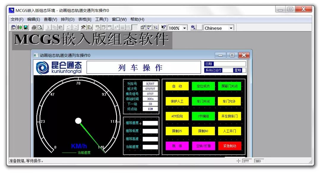
How do we use the touch screen? We need to program the touch screen, or say “configure” it. Programming requires using Kunlun Tongtai’s own configuration software: MCGS, which can be downloaded for free from its official website.
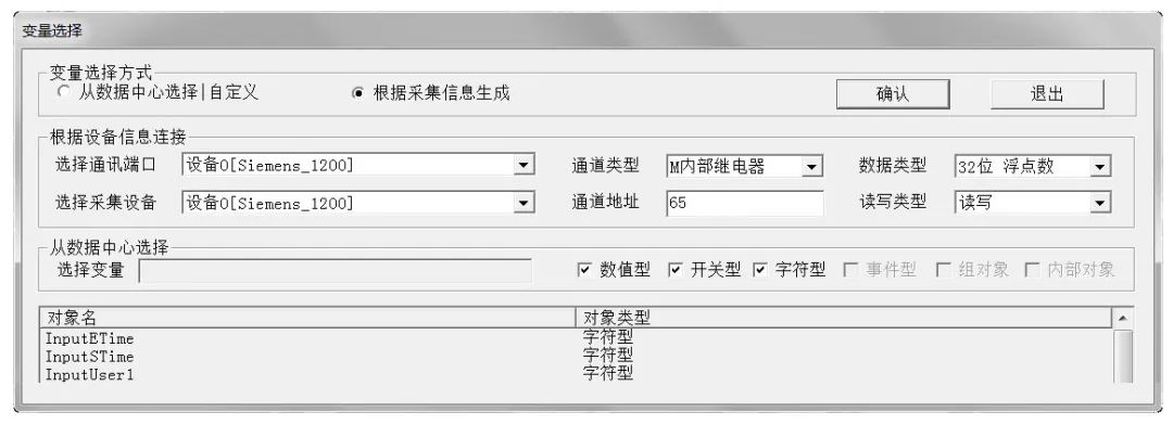
Install the software on your computer. Note that you need to enter the PLC’s address in the software to read and write data. The touch screen has only one network port, so you can connect the touch screen to your computer using a network cable. We note that the S1200 has two network ports, so a more convenient way to connect is to connect the touch screen to the S1200, and then connect the S1200 to your computer, which also allows programming of the touch screen. The most basic function of the touch screen is to read and write the PLC’s memory (thus it is also the host machine of the PLC). Achieving this function is very simple; you just need to associate the PLC’s variables in MCGS.
10.1 Programming Tool STEP 7
Purchasing the S1200 does not mean you can use its development software for free. But don’t worry, there are many cracked versions available online. Interestingly, some of these resources are deliberately released by people from Siemens, who may want to capture more market share. To program Siemens’ PLC, you must use dedicated software: STEP 7. The following is the installation process for STEP 7.
Nowadays, AGVs are increasingly equipped with touch screens. Using a touch screen allows for easy parameter settings of the AGV, such as motion speed, charging voltage, etc., without needing to download the program to the PLC each time. Since we chose Siemens PLC, it is of course best to choose a Siemens touch screen, but considering that Siemens touch screens are a bit expensive, we choose domestic brands. Domestic touch screens are also reliable in quality and reasonably priced, with representative manufacturers including Weilin and Kunlun Tongtai. Due to Siemens’ reputation, most touch screens will support it. However, if you use PLCs from other brands, it is best to ask the touch screen manufacturer whether they support your PLC, otherwise communication will not be possible.
I chose the touch screen from Kunlun Tongtai, which uses 24V DC power supply and is equipped with a network port. You can connect the touch screen and S1200 using a regular network cable and set the touch screen’s IP address to be in the same subnet as the PLC (for example, 192.168.0.3) to achieve interconnection with the PLC. The method for setting the IP is to click on any position on the screen before entering the formal interface after powering on.
How do we use the touch screen? We need to program the touch screen, or say “configure” it. Programming requires using Kunlun Tongtai’s own configuration software: MCGS, which can be downloaded for free from its official website.
Install the software on your computer. Note that you need to enter the PLC’s address in the software to read and write data. The touch screen has only one network port, so you can connect the touch screen to your computer using a network cable. We note that the S1200 has two network ports, so a more convenient way to connect is to connect the touch screen to the S1200, and then connect the S1200 to your computer, which also allows programming of the touch screen. The most basic function of the touch screen is to read and write the PLC’s memory (thus it is also the host machine of the PLC). Achieving this function is very simple; you just need to associate the PLC’s variables in MCGS.
10.1 Programming Tool STEP 7
Purchasing the S1200 does not mean you can use its development software for free. But don’t worry, there are many cracked versions available online. Interestingly, some of these resources are deliberately released by people from Siemens, who may want to capture more market share. To program Siemens’ PLC, you must use dedicated software: STEP 7. The following is the installation process for STEP 7.
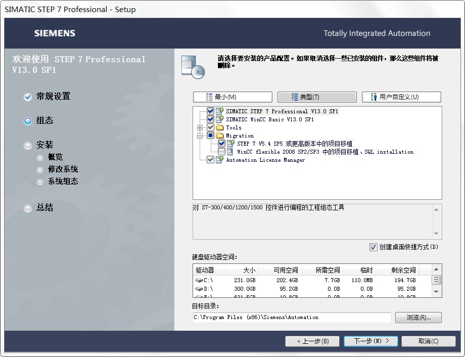
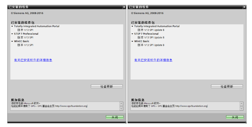
In fact, STEP 7 is an outdated name; now Siemens wants to unify it with several other automation software into a single platform suitable for all Siemens devices, called TIA Portal (博途). This article uses TIA V13. To maintain continuity, the software’s name is sometimes STEP 7 and sometimes TIA; for consistency with history, I will still call it STEP 7. Siemens’ software, like its hardware, comes in various types; there are several versions of STEP 7, such as the professional version (professional SP1, as shown in the left figure below), and each version has different update packages. Note that SP1 may lack certain features (as I will mention later), so I used an update package. Specifically, I used STEP 7 V13.0 SP1 Upd8, as shown in the right figure below.
During the software installation, we noticed a note: STEP 7 is an engineering configuration tool for programming. To use the PLC, programming is just one aspect; another important task is “configuration.” In simple terms, configuration means setting up the PLC’s input/output interfaces, parameters, functions, etc. First, select our PLC model on the “Device Configuration” page.
10.2 Hardware Resources of Siemens PLCTo make good use of the PLC, it is essential to understand some of its characteristics. Let’s take a look at the features of the S1215C.
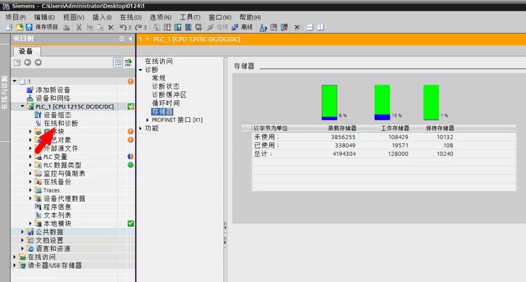
We connect the PLC to the computer, then double-click “Online and Diagnostics” in the left sidebar of TIA Portal software, and click “Memory” in the opened window, as shown in the figure below.
Here, we can see three types of memory: load memory, working memory, and retain memory. We can also see the size of the three types of memory, which are:
(1) Load Memory: 4194304 Bytes ÷1024÷1024= 4MB
(2) Working Memory: 128000 Bytes ÷1024= 125KB
(3) Retain Memory: 10240 Bytes ÷1024= 10KB
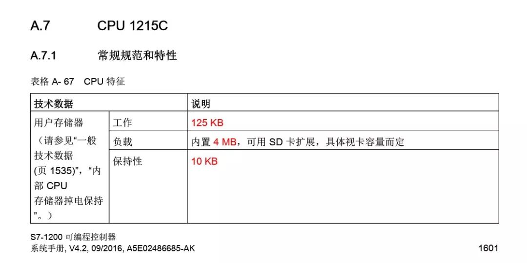
This matches the values given in the system manual, as shown below:
After seeing this, you might cry; even mobile phones from 10 years ago had larger storage. What are the functions of these three types of memory?
1) Load Memory: Used to store user project files (e.g., user programs, configuration information), equivalent to a hard drive;
2) Working Memory: The CPU copies some project content from the load memory to the working memory when executing the user program, equivalent to a computer’s RAM;
3) Retain Memory: Data remains after power loss. If you want certain data to persist after power loss, you need to use this memory. Unfortunately, the stingy Siemens only gave us 10KB.
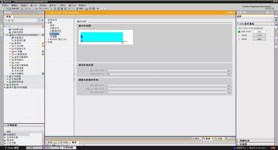
How long does it take for the PLC to scan a program once?
The PLC records the time automatically. On the same page, by opening “Cycle Time,” you can see how long it takes for the PLC to execute the program completely, as shown in the figure below. This time is not fixed; it depends on the length of your program, and the general execution time is within 3 milliseconds.
10.3 Software Resources of Siemens PLC
What function operations does Siemens provide? The only international standard for industrial control languages, IEC61131-3, specifies 46 basic functions, all of which are supported by Siemens. In addition, commonly used functions include timers, etc. AGVs belong to mobile robots, and the control of robots is essentially mathematical calculations, so I will focus on the mathematical functions, which total 18:
Numeric operations: ABS, SQRT, LOG, LN, EXP, SIN, COS, TAN, ASIN, ACOS, ATAN;
Arithmetic operations: ADD, SUB, MUL, DIV, MOD, EXPT, MOVE;
Of course, there are also: >, < comparison operators.
If you look at another controller brand’s manual, such as Beckhoff, you will find that it also supports these basic functions.
In the configuration interface, double-clicking the CPU module will reveal other features of this PLC, such as cycle timers, as shown in the figure below.
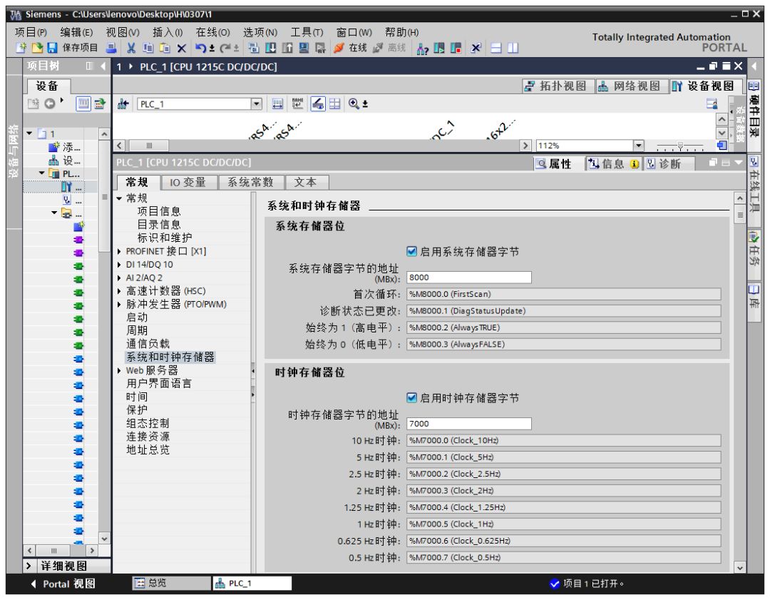
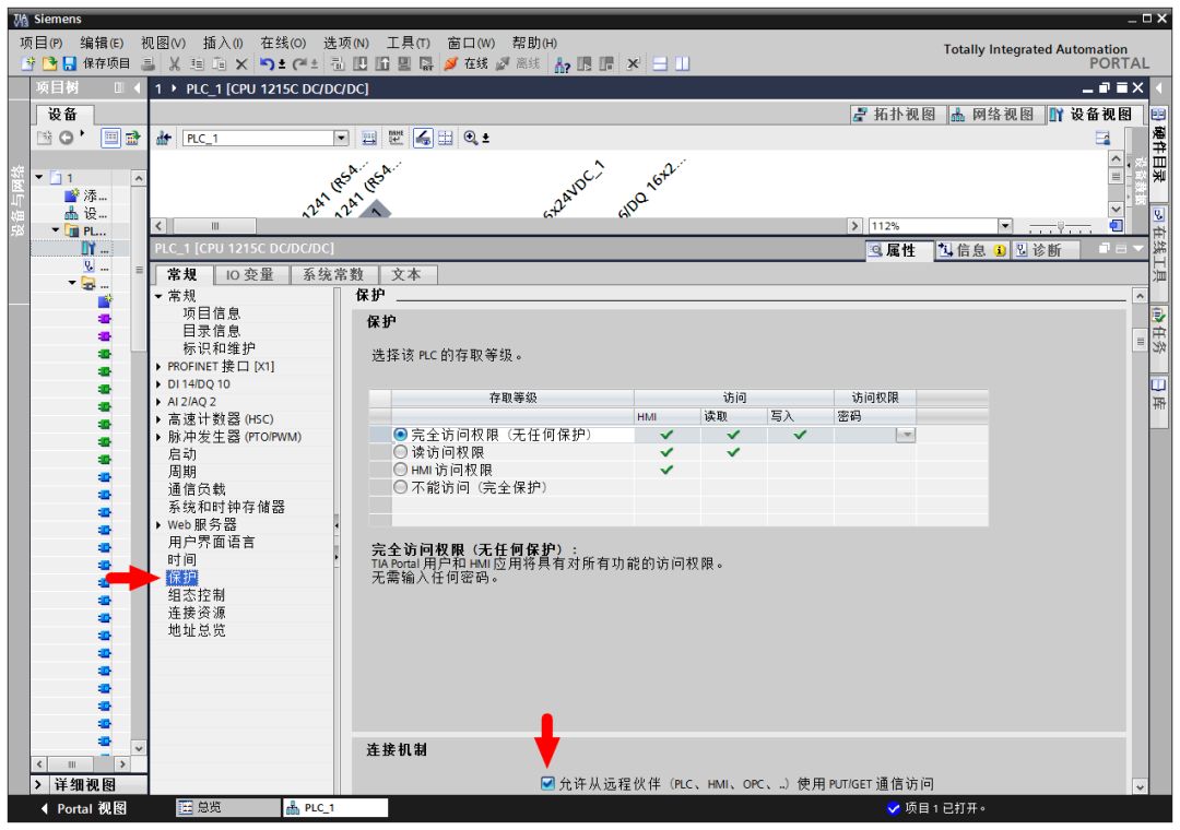
If you are using a touch screen, one thing to note is that in the “Protection” page, there is an option that needs to be checked: “Allow remote partners to access PUT/GET communication,” as shown in the figure below. If this option is not checked, you will not be able to read and write data from the PLC memory using the touch screen. The author is puzzled because such details are rarely found in manuals or tutorials but are very important.
10.4 Programming Methods for Siemens PLC
Siemens PLC programming complies with the international industrial programming language standard IEC-611313, so it is similar to that of Beckhoff and other manufacturers.
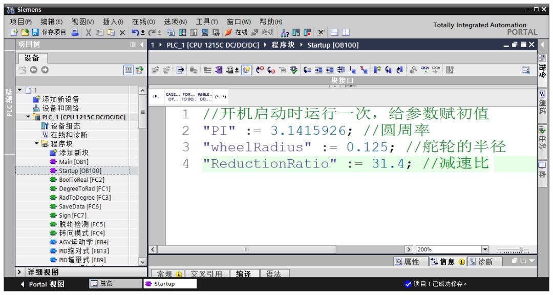
Some quantities are frequently used (e.g., pi), and if you use values for calculations each time, it is easy to make mistakes in input, and if you want to change it, you would need to change it in many places, which is cumbersome. A convenient approach is to define it as a global “constant.” Similar to PLC and high-level languages like C, you need to allocate memory addresses for variables. After allocating the address, how do you assign a value to it? Since constants only need to be assigned once, we choose to assign values in the Startup block. The Startup block executes only once every time the PLC is powered on. Some blocks in Siemens have reserved numbers by the system, such as Startup is OB100. We note that global variables are represented by double quotes (e.g., “PI”), while local variables are prefixed with a hash (#, which we will encounter later).
(2) Defining Functions
Siemens’ built-in functions can only complete simple functions, and to achieve more advanced control, we need to write our own functions. During the development of the robot controller, the author found that there are very few publicly available PLC function libraries, and currently, the only one known is the OSCAT library. While everyone discusses basic logical control, few discuss more advanced mathematical computations; perhaps PLCs are not suitable for implementing advanced motion control algorithms.
Below, I will illustrate how to define a simple function for converting angles to radians in STEP 7.
1) First, we create a function FC (this function is simple and does not require background data, so we do not need FB), and choose SCL language for implementation. The function name is “DegreeToRad”.
2) Next, we need to clarify the input of this function. In the variable definition bar above, input the project in the Input section as angleInDegree, and select the type as Real, as shown in the figure.
In the Return section, change the type of the DegreeToRad variable to Real, but be careful not to change the name of the DegreeToRad variable.
3) In the input box below, enter the conversion formula.
Here, use := to assign values to the variables. You will notice that the variable PI is enclosed in double quotes, while other variables (such as angleInDegree) are prefixed with a hash. This is to distinguish local variables from global variables, where local variables are indicated with #.
Timers are a function we often use; if you want to output quantities that change over time, trigger delays, or output periodic signals, you need to use timers. Each timer in Siemens corresponds to a background data block. One mistake I often made in the past was to copy and paste timer blocks directly to save time. The error was that no matter how many times you copy, it is still the same timer, and the latter will overwrite the value of the former. This mistake caused many inexplicable errors and troubled me for a long time. Everyone must note that each timer used must be dragged in to create a new one.
(4) Magnetic Line Following Algorithm
To ensure that the AGV always follows the magnetic strip, we need to write the corresponding control program, which is the line-following program.
The logic of the line-following program can be very simple: our input is the readings from the magnetic navigation sensor, and the output is the speed of the steering wheel (or the speed difference of the differential wheels). If the magnetic strip is to the left of the AGV’s centerline, we will turn left; if it is to the right, we will turn right; and if it is exactly in the middle, we will stay still. The following simulation animation demonstrates the effect of this control strategy, which uses only one sensor and one steering wheel but can already move along a curve. The magnetic navigation sensor has six points installed at the front, with the red squares indicating that the magnetic strip is sensed, while the white squares indicate no sensing.
For submissions, please click “Read the Original”

Responsible Editor: Duan Shaomin
Review: Li Guoqing
Source: Jicheng Training. If there are any copyright issues, please contact us in a timely manner. The interpretation of copyright belongs to the original author. This article is recommended for reading by Intelligent Manufacturing IMS!

PleaseFollowVideo Account
To Learn More About Intelligent Manufacturing News