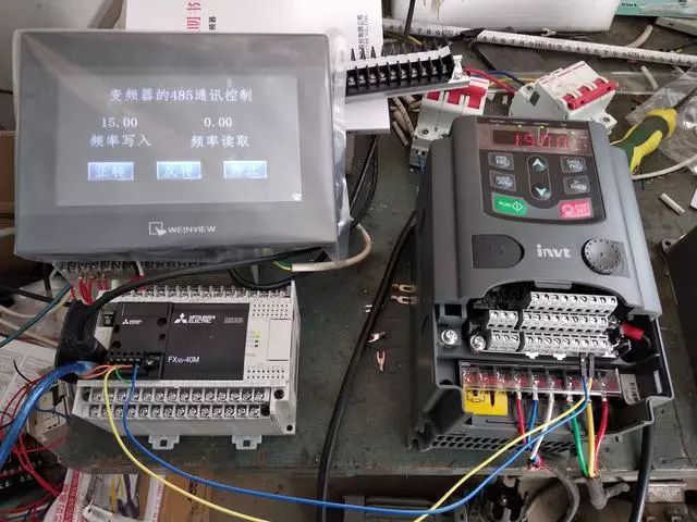
Required hardware: Mitsubishi FX3G PLC, RS485 communication module (FX3G-485BD), one Inovance inverter, touch screen (MT6071IP).
Required knowledge: PLC communication protocol, command sending, inverter communication parameter settings.

The wiring is quite simple. Insert the FX3G-485-BD module into the PLC, short SDB and RDB, short SDA and RDA. Connect the 485+ terminal of the inverter to the SDA and RDA of the module, and connect the 485- terminal of the inverter to the SDB and RDB of the module. The RS485 interface works in half-duplex mode, meaning that signal reading and writing cannot be sent simultaneously; when sending, reading cannot occur.
Wiring Diagram

Change the inverter’s run command and frequency command to MODBUS communication settings. In group P00, change P00.01 run command channel to 2: communication run command channel (default value 0), P00.07B frequency command selection to 8: MODBUS communication setting (default 2), and P00.09 set source combination mode to 1:B, with the current frequency set to B frequency command.
For communication parameters, in group P14, set the inverter’s station number to 1 in P14.00, set the baud rate to 9600 in P14.01, and set data bit parity to none (N, 7, 2) for ASCII.

1.Set in software (GX-Works2): Click on parameters in the navigation → PLC parameters → PLC system settings
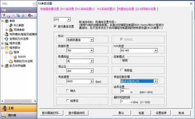
PLC System Parameter Settings
2.Use program settings
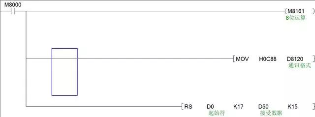
Ladder Diagram Parameter Settings
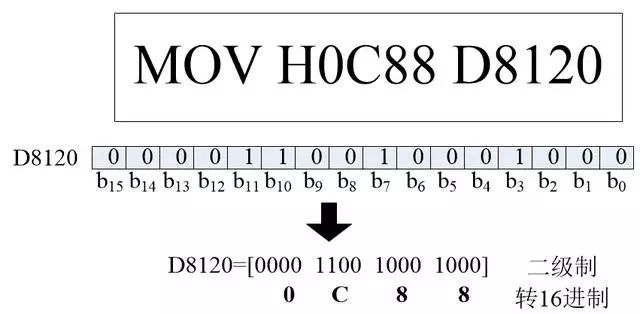
M8161=1, it is 8-bit operation, meaning to ignore the high 8 bits and only transmit the low 8 bits of data. The reason for this will be explained later. MOV HOC88 D8210 specifies the communication format, and we look at the content of D8120:
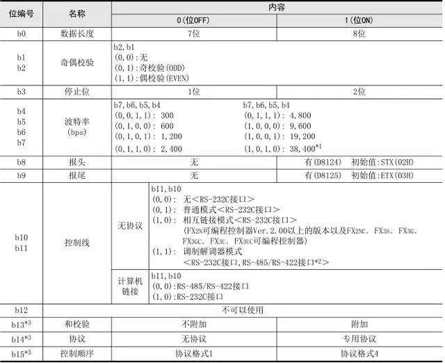
Content of D8120
D8210 is a 16-bit data, calculated based on the set parameters. For example, how H0C88 is derived, we look at the communication method, baud rate 9600, 7 data bits, no parity check, and stop bit is 2, control line is no protocol modem mode (RS485 interface):
Communication Parameter Calculation

Serial data transmission RS, hexadecimal conversion to ASCII code ASCI, ASCII code conversion to hexadecimal HEX.
RS:This command is used for unprotocol communication through the RS-232C or RS-485 serial communication port installed on the basic unit, thus executing data sending and receiving commands.
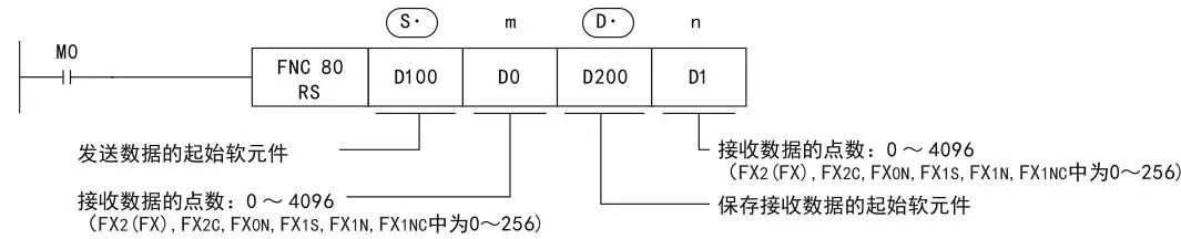
Example of RS
The RS command is used to specify the starting soft element and the number of data points for sending data from the FX programmable controller, as well as the starting soft element for saving received data and the maximum number of points that can be received. The programming follows these principles:
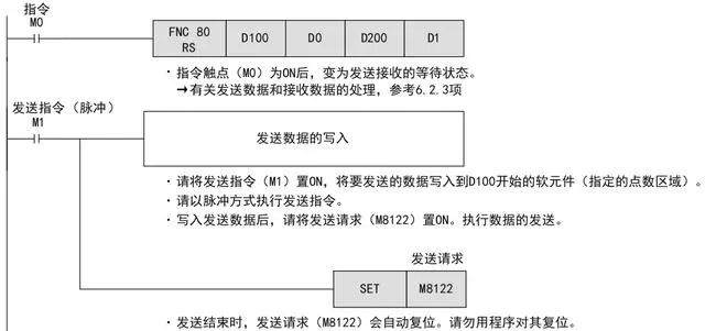
Send Command
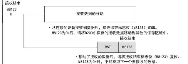
Receive Command
ASCII code uses a specified 7-bit or 8-bit binary array to represent 128 or 256 possible characters. The MODBUS protocol has two transmission modes, ASCII and RTU mode. This inverter uses ASCII mode for signal transmission, while the previous chapter’s HMI controlling the inverter uses RTU mode. Therefore, since ASCII mode is used, data format M8161 selects 8-bit data mode.

5.1 Inverter Function Description
Use ASCII mode to transmit data; in ASCII mode, the frame header is “:” (“0x3A”), and the frame tail defaults to “CRLF” (“0x0D” “0x0A”). In ASCII mode, except for the frame header and frame tail, all other data bytes are sent in ASCII code, first sending the high 4 bits, then sending the low 4 bits. Data in ASCII mode is 8 bits long. For ‘A’~’F’, use their uppercase ASCII codes. At this point, data uses LRC check, covering the information from the slave address to the data part. The checksum equals the two’s complement of the sum of all characters involved in the check (discarding carry bits).

MODBUS Message
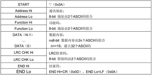
Standard Structure of ASCII Frame

Function Description

6.1 Communication Settings
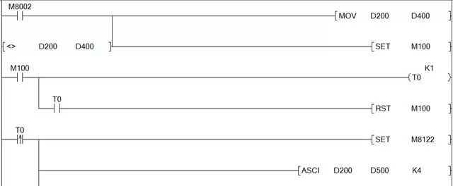
This is the ladder diagram for setting PLC communication parameters
6.2 ASCII Code Conversion
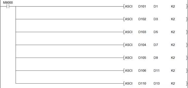
ASCII Code Conversion
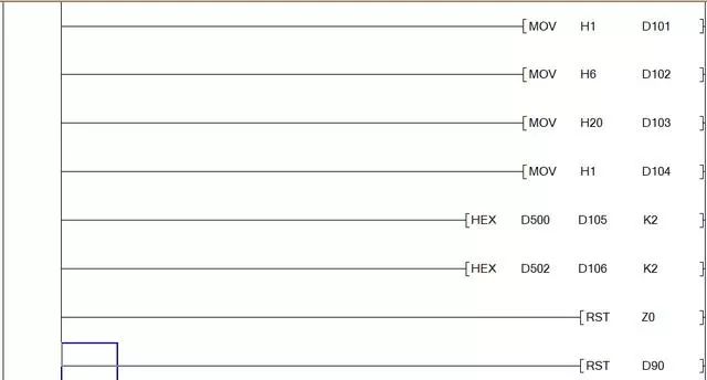
Convert data to ASCII code according to the standard structure of the ASCII frame, starting character START: 3AH
Address: the station number, composed of two ASCII codes, for example, station number 1, the address is 01H, converted to ASCII code is 30, 31, PLC monitoring:
The program displays in decimal
Function Code: indicates whether to write data or read data, composed of two ASCII codes, writing is 06H, reading is 03H.
Function Code Address: is the address for writing or reading, composed of two ASCII codes.
Data Content DATA: is the content to be written or read, composed of 2n ASCII codes.
LRC Check Value: LRC checksum, composed of two ASCII codes
End Character: END Hi=0DH, END Lo=0AH.
RS D0 K17 D50 D15 is the command to send the above content, where D0 is the start character, D1D2 is the address, D3D4 is the function code, D5D6 is the command code high address, D7D8 is the command code low address, D9D10 is the data content high address, D11D12 is the data content low address, D13D14 is the LRC check code, D15D16 is the end character.
6.3 Writing Data
Writing Data
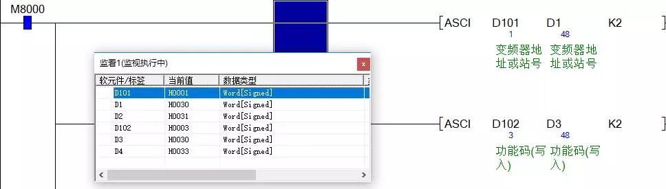
M8122 is the send command, indicating that information is being sent, ASCI D200 D500 K4. D200 is the frequency data, converting D200 data to ASCII, for example, D200=0ABCH, K4 indicates D500=0, D501=A, D502=B, D503=C, converting only 4 digits.
D101 is the station number, D102 is the function code, D103D104 are the function code high and low addresses, D105D106 are the data content.
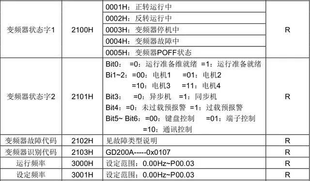
Based on the inverter’s MODBUS function, we know that the address for writing frequency is 2001H, thus high bit 20H is sent to D103, low bit 01H is sent to D104, and then the frequency value is sent to D105D106, resetting the LRC value after transmission.
This completes the write function; the inverter’s forward and reverse stop functions are programmed in order according to the above table.
6.4 Reading Data
Since half-duplex operation is used, writing and reading cannot occur simultaneously,
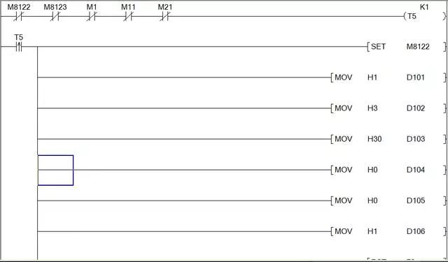
Data Reading
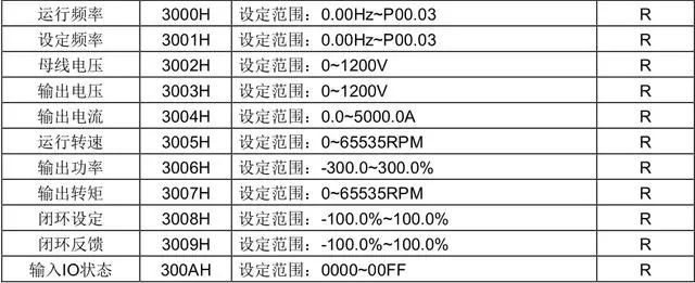
This means that when reading data, the sending, receiving, and writing commands must be completed unexpectedly. To check the inverter function table, the address for reading frequency is 3000H.
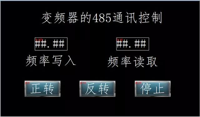
HMI Interface
Disclaimer: This article is reproduced from the internet, and the copyright belongs to the original author. If there are any copyright issues, please contact us in time to delete it. Thank you!
Complete question bank for the 2021 electrician primary examination (including answers)
Three must-have tools for electrical workers, just one click on WeChat to use!
[Collection] The “way out” for a ten-year veteran electrician, the secret to earning over ten thousand a month!
The five major electrical drawing software (CAD, Eplan, CADe_simu…), which one do you pick?
The latest electrical version CAD drawing software, with super detailed installation tutorial!
The latest electrical drawing software EPLAN, with super detailed installation tutorial!
Common problems for beginners using S7-200 SMART programming software (with download link)
Comprehensive electrical calculation EXCEL sheets, automatically generated! No need to ask for electrical calculations!
Bluetooth headphones, electrical/PLC introductory books are freely given away? Come and get your electrical gifts!
Basic skills in PLC programming: Ladder diagrams and control circuits (with 1164 practical cases of Mitsubishi PLC)
Still can’t understand electrical diagrams? Take away the basic electrical recognition and simulation software, quickly get started with theory and practice!
12 free electrician videos, 10GB software/eBook materials, and 30 days of free electrician live classes are being given away!