 1. Working Principle
Eddy current sensors can be divided into high-frequency reflective and low-frequency transmissive types. Below, we will elaborate on their working principles:Eddy current sensors operate based on the principle of electromagnetic induction, but they are fundamentally different from traditional electromagnetic induction, and in practical measurements, it is essential to avoid interference from electromagnetic induction.
Formation of Eddy Currents: Assume there is a coil with a core made of a solid ferromagnetic material. This core can be considered as composed of many closed loops perpendicular to the magnetic flux, thus forming numerous closed circuits. When alternating current flows through the coil, the magnetic flux through the core varies periodically with the current, resulting in induced electromotive force in these closed circuits. Under the influence of this electromotive force, many vortex-shaped currents are formed, which are referred to as eddy currents.
The working principle of the eddy current sensor is illustrated in the figure below:
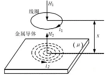
When high-frequency currenti flows through the coil, a high-frequency magnetic field is generated around the coil. This magnetic field acts on the metal body, but due to the skin effect, it cannot penetrate through a metal body of a certain thickness and only acts within a thin layer on the metal surface. Under the influence of the alternating magnetic field, an induced currentIe is generated on the metal surface, which is the eddy current. The induced current also generates an alternating magnetic field that reacts back on the coil, with a direction opposite to that of the original magnetic field of the coil. The superposition of these two magnetic fields alters the original impedance of the coilZ, and the change inZ is only related to the resistivity of the metal conductorρ, permeabilityu, excitation electromagnetic intensityi, frequencyf, the geometric shape of the coilr, and the distance between the coil and the metal conductor. The impedance of the coil can be expressed as the following function:Z=F(ρ,u,i,f,d). When the material of the object being measured is fixed,ρ,u are constants, and the values ofi,f,d are also fixed, thusZ becomes a single-valued function of the distanced.
2. Practical Applications
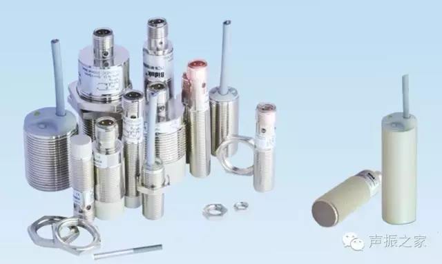
Eddy current sensors are widely used due to their large measurement linear range, high sensitivity, simple structure, strong anti-interference capability, and insensitivity to contaminants such as oil, especially in non-contact measurements.In thermal power plants, they are mainly applied in the following monitoring projects:
1. Rotor Speed: During the operation of the unit, the rotor speed is continuously monitored, and an alarm signal or shutdown signal is issued when the speed exceeds a specified value. The working principle: According to the working principle of the eddy current sensor, a periodic pulse is generated between the proximity eddy current probe and the rotating rotor gear, and measuring this periodic pulse allows for monitoring of the rotor speed.
2. Rotor Zero Speed: Zero speed indicates that the unit is operating below the minimum rotational speed, which is to prevent the rotor shaft from bending due to gravity during shutdown. The working principle is the same as that of the rotor speed.
3. Eccentricity: The eccentricity of the rotor indicates its bending due to thermal stress, observed during the gear mechanism’s rotation, providing reliable and accurate monitoring data for rotor misalignment. The eddy current probe can continuously monitor the peak-to-peak value of the eccentricity, which is synchronized with the key phase pulse. The working principle: The eccentricity probe is installed at the shaft neck of the turbine’s front bearing box, with its core part being an inductive coil. When the main shaft rotates, if there is eccentricity, the distance between the shaft and the inductive coil changes periodically, causing periodic changes in the inductance of the inductive coil. By measuring this change in inductance, the eccentricity of the shaft can be determined.
4. Key Phase: Key phase is a physical quantity that describes the position of the rotor at a specific moment. The key phase probe and the eccentricity probe together monitor the eccentricity of the main shaft, accurately reflecting the specific phase angle of the eccentricity. The working principle: Key phase measurement is achieved by setting a groove or protrusion on the measured shaft, referred to as the key phase mark. When this groove or protrusion rotates to the probe position, it corresponds to a change in distance between the probe and the measured surface, causing the sensor to generate a pulse signal. A pulse signal is generated for each complete rotation of the shaft, indicating the position of the shaft within each rotation cycle. Therefore, by comparing the pulse signal with the vibration signal of the shaft, the phase angle of the vibration can be determined.
5. Vibration: The eddy current probe primarily monitors the relative vibration of the main shaft concerning the bearing seat. The working principle: The change in distance between the coil of the eddy current probe and the measured metal body can be converted into changes in three electrical parameters: equivalent inductance, equivalent impedance, and quality factor of the coil. With the corresponding preamplifier, these three electrical parameters can be further converted into voltage signals, enabling vibration measurement.Vibration can be caused by several factors:
-
Vibration caused by misalignment during unit operation. If the vacuum decreases during operation, it will raise the temperature of the exhaust steam, lifting the rear bearing and thus causing vibration due to misalignment.
-
Vibration caused by unbalanced rotor mass.
-
Vibration caused by elastic bending of the rotor.
-
Vibration caused by unstable oil film in the bearings.
-
Vibration caused by internal friction in the turbine.
-
Vibration caused by water impact.
-
Vibration occurring when the turbine reaches critical speed.
6. Axial Displacement: Axial displacement refers to the gap between the internal rotor of the unit and the thrust bearing along the axial direction. By measuring axial displacement, it can indicate the axial gap or relative instantaneous axial change between rotating and stationary components. Its working principle is similar to that of vibration measurement, but it should be noted that axial displacement measurement is often confused with axial vibration. Axial vibration refers to the rapid change in distance between the surface of the sensor probe and the measured body along the axial direction, represented by peak-to-peak values, which is unrelated to the average gap.
7. Thermal Expansion Difference: During operation, the rotor expands due to heating. Since the rotor is constrained by the thrust bearing, it can only extend axially towards the low-pressure side. Due to the small volume of the rotor and its direct exposure to steam impact, the heating and thermal expansion occur rapidly, while the cylinder has a larger volume and heats and expands more slowly. Before the thermal expansion of the rotor and cylinder stabilizes, the existing thermal expansion difference is referred to as thermal expansion difference. Regarding the direction of thermal expansion difference: during unit startup or load increase, it is a heating process of steam on the metal, where the rotor heats up faster than the cylinder, and the thermal expansion value greater than that of the cylinder is called positive thermal expansion difference. During shutdown or load reduction, it is a cooling process where the rotor cools faster than the cylinder, resulting in the axial expansion value of the rotor being less than that of the cylinder, referred to as negative thermal expansion difference.
3. Installation of Eddy Current Sensors
(1) Installation Considerations
-
Gap for probe installation.
-
Safety distance between the probe head and the mounting surface.
-
Sealing and insulation of cable connectors.
-
Corrosion resistance of the probe.
-
Minimum distance between probes.
-
Stability of the probe mounting bracket.
-
Installation of cables attached to the probe and extended cables.
-
High temperature and pressure environment for the probe.
(2) Factors Affecting Sensor Characteristics
① Surface Flatness of the Measured Body Affecting the Sensor
Irregular surfaces of the measured body can introduce additional errors in actual measurements; therefore, the surface of the measured body should be smooth and flat, without protrusions, holes, scratches, or grooves.
② Magnetic Effects of the Measured Body Surface Affecting the Sensor
The eddy current effect mainly concentrates on the surface of the measured body. Residual magnetic effects formed during processing, as well as uneven quenching, hardness, and crystalline structure, can all affect sensor characteristics.
③ Coating on the Measured Body Surface Affecting the Sensor
The coating on the surface of the measured body affects the sensor as if it changes the material of the measured body. Depending on the material and thickness of the coating, the sensitivity of the sensor may vary slightly.
④ Size of the Measured Body Surface Affecting the Sensor
Since the magnetic field generated by the probe coil has a certain range, and the eddy currents formed on the surface of the measured body are also limited, there are certain requirements for the size of the measured body surface. Typically, when the surface of the measured body is flat, the diameter of the measured surface should be more than 1.5 times the diameter of the probe head, centered on the probe’s centerline. When the measured body is a circular shaft and the probe’s centerline is orthogonal to the shaft centerline, the diameter of the measured shaft should generally be more than three times the diameter of the probe head; otherwise, the sensitivity of the sensor will decrease. The smaller the surface of the measured body, the more the sensitivity decreases. Experimental tests show that when the size of the measured body surface is the same as the diameter of the probe head, its sensitivity can drop to about 72%. The thickness of the measured body also affects the measurement results. The depth of the eddy current field’s action in the measured body is determined by frequency, material conductivity, and permeability. Therefore, if the measured body is too thin, it will cause insufficient eddy current action, leading to decreased sensor sensitivity.
(3) Sensor Installation Requirements
① Requirements for Operating Temperature
Generally, the maximum allowable temperature for eddy current sensors is ≤180°C. In practice, if the operating temperature is too high, not only will the sensitivity of the sensor significantly decrease, but it may also cause damage to the sensor. Therefore, when measuring the vibrations of high, medium, and low-speed shafts of turbines, the sensor must be installed within the bearing shell; only specially designed high-temperature eddy current sensors are allowed to be installed near the steam seal.
② Requirements for the Measured Body
To prevent the magnetic field generated by the eddy currents from affecting the normal output of the instrument, a certain range of non-conductive medium space must be left around the probe head during installation. If two or more sensors need to be installed simultaneously at a certain location during testing, a certain distance should be maintained between the two sensors to avoid cross-interference. Additionally, the surface area of the measured body should be more than three times the diameter of the probe, and the surface should not have scars, small holes, or gaps, and surface plating is not allowed. The material of the measured body should be consistent with that of the probe and the material calibrated for the preamplifier.
③ Requirements for the Probe Bracket
The probe is fixed to the bearing seat via a bracket, which should have sufficient rigidity to increase its natural frequency and avoid or minimize the self-excited vibration of the bracket when the measured body vibrates.
④ Requirements for Initial Gap
The eddy current sensor should have a good linearity of readings at a certain gap voltage (the gap between the top of the sensor and the measured object, generally indicated as voltage on the instrument), so the appropriate initial gap must be adjusted during sensor installation.
After the rotor rotates and the unit is loaded, the rotor will displace relative to the sensor. If the sensor is installed at the top of the bearing, the gap will decrease; if installed in the horizontal direction of the bearing, the gap will depend on the direction of rotor rotation; when the direction is fixed, the gap will depend on whether it is installed on the right or left side. To obtain the appropriate working gap value, the displacement value and direction of the shaft neck from static to rotating state under load should be estimated during installation to consider when adjusting the initial gap. According to field experience, the shaft neck typically rises about 1/2 of the bearing gap from static to operating speed; the horizontal displacement is related to the type of bearing, the gap on both sides of the bearing, and the working state of the unit’s sliding pin system, generally ranging from 0.05 to 0.20mm.
When adjusting the initial gap of the sensor, in addition to considering the above factors, the maximum vibration value and the original sway value of the rotor should also be taken into account. The initial gap of the sensor should be greater than 1/2 of the maximum amplitude that the rotor may experience and the original sway value of the rotor.
(4) Installation Steps
① Before inserting the probe into the installation hole, ensure that there are no foreign objects inside the hole, allowing the probe to rotate freely without entangling with wires.
② To avoid scratching the probe tip or the monitored surface, a non-metallic feeler gauge can be used to determine the probe’s gap.
③ It is also possible to adjust the probe gap using the electrical method by connecting the probe wire to the extended cable and preamplifier.
Once the probe gap is appropriately adjusted, tighten the anti-loosening nut. At this point, care should be taken not to overtighten, as this may damage the threads. After the probe is secured, the probe’s wire should also be firmly attached. The length of the extended cable should match the required length for the preamplifier. Any extension or shortening may lead to measurement errors.
The preamplifier should be placed in a cast aluminum box to prevent mechanical damage and contamination. No excess cables should be attached to the box, and multiple preamplifiers can be installed in the same box without changing the cable length from the probe to the preamplifier to reduce installation costs and simplify wiring from the preamplifier to the monitor. Appropriate isolation and shielding grounding should be used to minimize signal interference.
(5) Installation of Extended Cables
Extended cables, as the intermediate connection between the probe and the preamplifier, are an important component of the eddy current sensor. Therefore, the installation of extended cables should ensure they are not easily damaged during use and should avoid high-temperature environments. The connection between the probe and the extended cable should be secured, and the joint should be wrapped with heat shrink tubing to avoid grounding and prevent loosening. When winding the extended cable, care should be taken to avoid a small winding radius that could damage the cable. Generally, the winding diameter of the extended cable should not be less than 55mm.
(6) Installation of the Preamplifier
The preamplifier is the signal processing part of the entire sensor system, and it should be installed away from high-temperature environments. The surrounding environment should be free of significant steam and water droplets, corrosive gases, dry, with minimal vibration, and the ambient temperature around the preamplifier should be close to room temperature. During installation, the metal part of the preamplifier housing should not contact the machine casing or ground. It is essential to avoid any other interference signals affecting the measurement circuit during installation.
(7) Locking the Installation Gaps for Speed, Zero Speed, Eccentricity, and Key Phase Sensors
These four types of sensors can use feeler gauges to measure the installation gap. A feeler gauge of the specified installation gap thickness is inserted between the probe end face and the measured surface, with the installation gap for these four types of sensors being approximately 1.3mm. When the probe end face and the measured surface compress the feeler gauge, the probe can be secured.
(8) Locking the Installation Gap for Axial Vibration Sensors
Connect the probe, extended cable, and preamplifier, and power the sensor system. Use a high-precision multimeter to monitor the output voltage of the preamplifier while adjusting the gap between the probe and the measured surface. When the output voltage of the preamplifier is approximately 10-11VDC, tighten the two fastening nuts of the probe to secure it.
(9) Zero Position Locking for Axial Displacement
① Measurement Principle of the Axial Displacement Monitoring System:
The axial displacement monitoring system utilizes the relationship between the output voltage of the eddy current sensor and the vertical distance to the measured metal surface within a certain range, converting the displacement signal into a voltage signal sent to the monitor, thus achieving monitoring and protection.
② Zero Position Locking of the Axial Displacement Sensor:
Factors to consider for zero position locking of the axial displacement sensor:
-
Gap △ value of the main shaft thrust bearing
-
Position of the main shaft (i.e., whether the main shaft thrust plate is resting on the working or non-working surface of the thrust bearing)
-
Calibration data of the displacement monitor and sensor
Given:△=0.36mm, the range of the axial displacement monitor is ±1.25mm, and the main shaft thrust plate is resting on the working surface.
The axial displacement should be calculated based on the zero position voltage of the sensor for accurate locking. Taking a 11mm sensor as an example, given: △=0.36mm, the main shaft thrust plate is resting on the working surface, the range of the axial displacement monitor is ±1.25mm, and the sensor sensitivity F=4.0V/mm, the calculation for the zero position voltage X is:
X=Vo-F×1/2×△=9.28V
After the final zero position locking, the monitor should display -0.18mm.
Note: If the main shaft thrust plate is resting on the non-working surface of the thrust bearing, X should be calculated as follows:
X=Vo+F×1/2×△=10.72V
Finally, install and lock the sensor according to the calculated X value, and the monitor should display 0.18mm.
③ Issues to Note During Field Installation and Debugging of Sensor Zero Position Locking:
a. If the thrust bearing gap is not considered, the meter will produce a measurement error of 1/2×△mm.
b. If the thrust gap of 1/2×△mm is reversed, the meter will produce a measurement error of △mm.
4. Common Faults and Handling Methods for Eddy Current Sensors
(1) Common Faults
-
Eddy current probe damage.
-
Loose connection between the probe wire and the extended cable.
-
Loose connection between the extended cable and the preamplifier.
-
Faults in the preamplifier or extended cable.
-
Grounding of the extended cable.
-
Poor insulation at the connection between the probe wire and the extended cable leading to grounding.
(2) Handling Methods
-
Replace the eddy current probe.
-
Tighten the connection between the probe wire and the extended cable.
-
Tighten the screws connecting the extended cable and the preamplifier.
-
Replace the preamplifier or extended cable.
-
Replace the extended cable or insulate the damaged grounding part with insulating tape.
-
Wrap the connection between the probe wire and the extended cable with heat shrink tubing.
(3) Suggestions for Handling Common Faults
-
When replacing the eddy current probe, care should be taken to avoid damaging the probe and not to wrap the connecting wire multiple times.
-
The connection between the probe wire and the extended cable has a locking function; when tightening, avoid excessive force to prevent damaging the lock.
-
When tightening the screws connecting the extended cable and the preamplifier, do not apply excessive force to avoid stripping the screws.
-
The replaced preamplifier should match the model of the probe and extended cable, and it should be placed in a cast aluminum box to avoid interference signals affecting measurement accuracy.
-
When replacing the extended cable, ensure that the winding diameter is not too small to avoid damaging the cable. Generally, the winding diameter should not be less than 55mm.
-
When handling the connection between the probe wire and the extended cable, use heat shrink tubing instead of electrical tape, as oil mist can dissolve the adhesive on the tape and contaminate the joint. When needing to open the connection, a small cut can be made at the metal part of the joint, taking care not to damage the cable.
(4) Potential Hazards When Handling Common Faults
-
Accidental contact with other operating equipment; staff should supervise each other.
-
High-temperature burns when replacing vibration probes; protective gloves should be worn.
-
Damage to the cable due to too small a winding diameter when replacing the extended cable; the winding diameter should not be less than 55mm.
-
Damage to the probe when replacing it; staff should take appropriate protective measures.
-
Damage to the probe due to excessive temperature; the working temperature of the probe should generally be less than 180 degrees, and only specially designed high-temperature eddy current sensors are allowed to be installed near steam seals.
Source: Thermal Control Circle
Disclaimer: If there are any copyright issues with the videos, images, or text used in this article, please inform us immediately, and we will confirm the copyright based on the materials you provide and delete the content promptly!
Disclaimer: If there are any copyright issues with the videos, images, or text used in this article, please inform us immediately, and we will confirm the copyright based on the materials you provide and delete the content promptly!