The role of encoders is something that everyone often hears about, but many people may only have a vague understanding of how to use them. Today, Teacher Chen will share with you the specific usage methods. Before using encoders, we need to first learn about the concept of high-speed counters.
1. What is a high-speed counter?
If our PLC’s X0 point is connected to a button, and we write the following program in the PLC, if we press the button once, the counter will record 1, if we press it twice, it will record 2, and so on. If we press it 1000 times, the normally open contact of counter C0 will close, which is easy to understand.

If I press once per second, then by manually pressing, I can achieve 1000 presses to close the contact.
The key point is that if I do not connect a button, but instead connect a photoelectric sensor or encoder to sense, triggered by the machine, the machine may operate at a very high speed, possibly pressing hundreds or even thousands of times per second. Our X0’s normally open contact may not be able to sense this, so what should we do? We can use a high-speed counter.
The table below shows our single-phase high-speed counter.
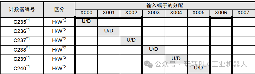
If I connect the photoelectric sensor to X0, then C235 is its dedicated counter. Every signal sensed by X0 will be counted by C235. We can use the following program to store the pulse count sensed by X0 into D235. (Similarly, C236 records the pulse count of X1; C237 records the pulse count of X2, etc.)

Of course, the counting frequency of the counter has a limit. The ordinary FX series X points can accept a speed of 50KHz, which means it can receive 50,000 activations in one second. .
Next, let’s see how to use the encoder.
2. Usage of Encoders (Relative Value Encoders)
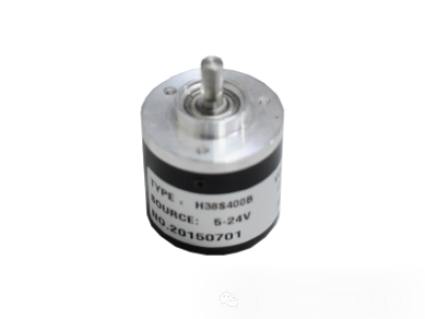 The right image shows an encoder. By rotating the shaft above, it can emit two signals. For every certain angle of rotation, these two outputs will close a certain number of times, just like the wiring of the photoelectric sensor above, which can be connected to two X points. Then we can
use a high-speed counter to count it, thus knowing how far it has rotated. This is different from the previous sensor that has a single input point; the encoder will increase the count when rotating forward and decrease the count when rotating backward.
For accurate positioning, we need to use another type of high-speed counter as shown below:
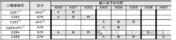
We can choose counters C251 to C255. If my encoder is connected to X0 and X1 (the wiring will be discussed later), then the selected one is C251. Let’s write a program to see:

In this way, we have recorded the position of the encoder in registers D0 and D1.
Finally, let’s take a look at the wiring.
3. Wiring of the Encoder
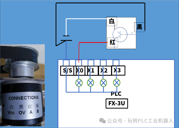
As shown in the figure, we choose a type of encoder for wiring, first let’s look at the principle.
For morePLC videos, you can scan the code to watch:

Disregarding the green wire of phase B, the white, black, and red wires actually function like an NPN-type sensor. The white and black wires are power supply wires, while the red wire serves as the output connected to the X0 point. When the encoder is activated, it outputs a low level to X0, which we name phase A.
The green wire is another sensing point of the encoder, which we can connect to X1. Its function is the same as the red wire of phase A, but it is offset in position, which we call phase B. Thus, once the encoder rotates, phases A and B will sense signals, and counting will be done through C251.
The resolution of this encoder is 400, meaning that for one full rotation, C251 counts 400. We can use this to determine how many rotations the motor has made, thus determining the position of the motor.
For a detailed explanation of encoders and high-speed counters, you can watch the following video.