S7-1200 PLC
Hardware Configuration
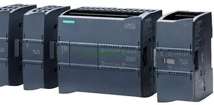
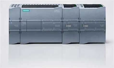
The Siemens S7-1200 PLC is a compact programmable logic controller widely used in the field of industrial automation. Its hardware and configuration form the foundation of control systems.
1.Hardware Components of S7-1200 PLCHardware Composition
1. CPU Module
Function: Core processing unit responsible for executing user programs, processingI/O data and communication.
Models: Such asCPU1211C,1212C,1214C,1215C,1217C, etc., the larger the number, the stronger the function.
I/O Quantity: The CPU has integratedI/O (e.g.,1214C has 14DI/10DO,2AI).
Supports expansion: Some models support expansion modules (e.g.,1212C can expand up to8 modules,1217C supports more).
Communication interface: IntegratedPROFINET interface (supports Ethernet communication and HMI connection).
 2. Signal Module (SM)
Digital Module:
DI Module: Such asSM1221 (digital input,8/16 channels).
DO Module: Such asSM1222 (digital output, transistor/ relay type).
Analog Module:
AI Module: Such asSM1231 (4-channel analog input, ±10V or 20mA).
AQ Module: Such asSM1232 (2-channel analog output).
3. Communication Module (CM/CB)
Communication Module (CM):
Such asCM1241 (RS232/RS485 communication module), supports Modbus RTU, USS protocol.
Communication Board (CB):
Such asCB1241 (inserted in the CPU front cover, adds RS485 interface).
4. Power Module (PM/PS)
PM1207: 24VDC power module, supplies power to CPU and expansion modules.
PS1207: External power adapter (optional).
5. HMI Panel (optional)
Such asKTP400 Basic,TP700, etc., directly connected to CPU through PROFINET.
2. Hardware Configuration
Hardware configuration is completed through TIAPortal software, the steps are as follows:
1. Create a new project
In TIAPortal, create a new project, select PLC model (e.g., CPU1214CDC/DC/DC).
2. Add CPU Module
Configure CPU properties:
PROFINET interface: Set IP address, subnet mask.
Startup mode: Choose “Warm Start RUN” or “Warm Start STOP“.
System clock: Enable clock memory (e.g., MB0).
3. Add expansion modules
Drag and drop expansion: In the device view, drag the signal module (e.g., SM1221), communication module (e.g., CM1241) to the right side of CPU.
Configure module parameters:
Digital module: Set input filter time or output hold state.
Analog module: Select range (e.g., 0-10V), filter parameters.

4. Communication Configuration
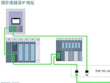
PROFINET Network:
Add HMI or remote I/O devices (e.g., ET200SP), assign device names and IP.
Serial communication (e.g., CM1241):
Configure baud rate, data bits, parity, bind protocol (e.g., Modbus RTU master).
5. I/O Address Allocation
Automatic allocation: TIAPortal defaults to allocate I/O addresses (e.g., %I0.0%I1.7, %QW100).
Manual modification: Adjust address range as needed.
6. Generate System Block
Click “Compile” to generate hardware configuration data
END