
Click the blue text
Follow us
UART (Universal Asynchronous Receiver/Transmitter)
-
The full name of UART is Universal Asynchronous Receiver/Transmitter.
-
UART is an asynchronous transceiver, a key module for asynchronous communication between devices. It handles the serial/parallel and parallel/serial conversion between the data bus and the serial port, and specifies the frame format.
-
As long as both parties use the same frame format and baud rate, communication can be completed using only two signal lines, RX and TX, without sharing a clock signal, which is a typical asynchronous serial communication.
-
UART can achieve full-duplex transmission and reception.
Adding an ‘S’ indicates synchronous (USART – Universal Synchronous/Asynchronous Receiver/Transmitter).
Synchronous communication: has a common reference clock.
Asynchronous communication: does not have a common reference clock, transmitting at a fixed baud rate.
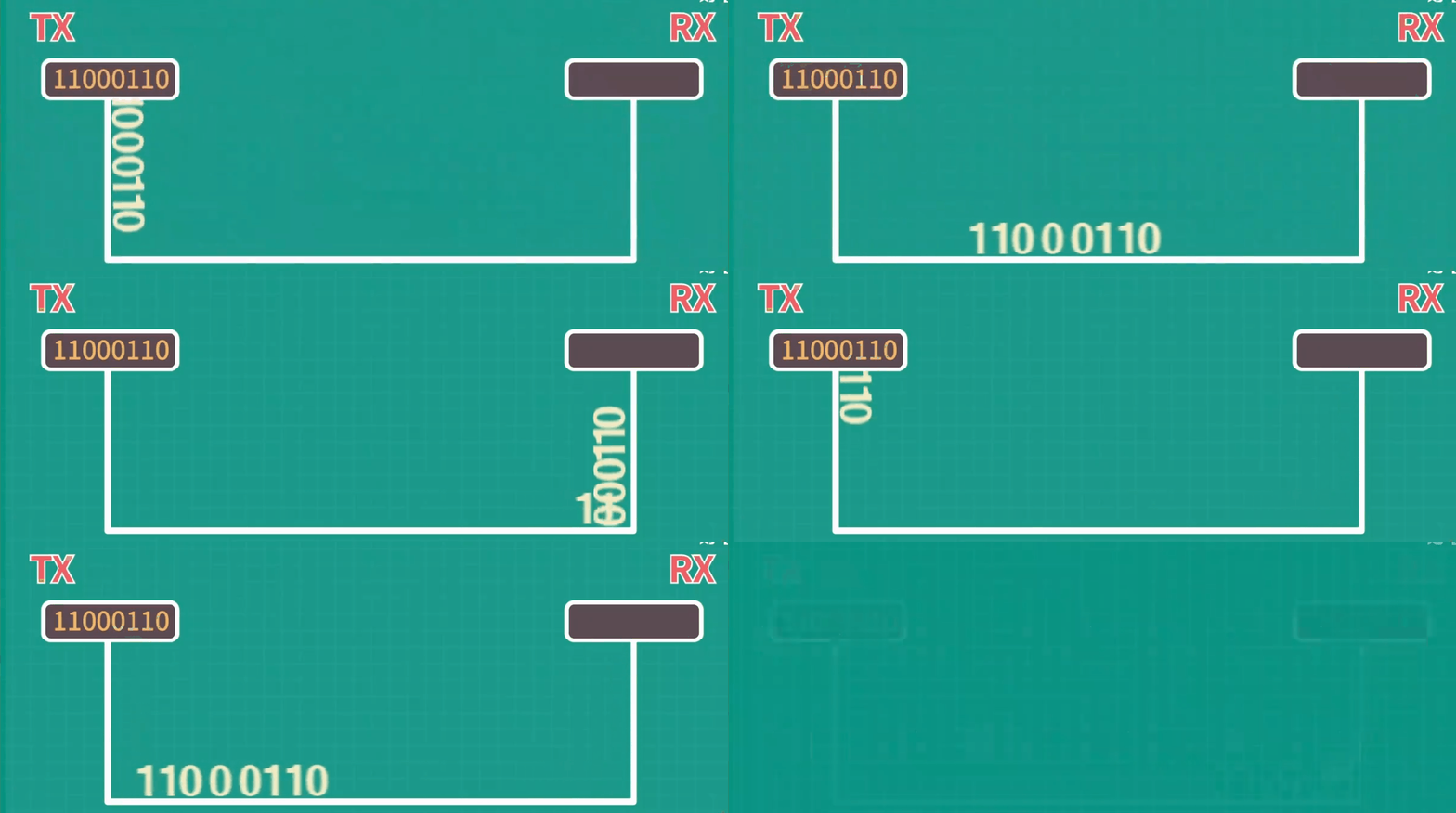
Characteristics
-
Universal Serial Asynchronous Transceiver, full-duplex communication.
-
TTL level standard: +3.3/+5 represents 1, 0V represents 0.
-
Both parties need to agree on the transmission baud rate (since there is no clock line).
-
The idle bit is high.
-
Cannot continuously send data; a maximum of 5-8 bits can be sent at once (to prevent error accumulation, as there is no clock line).
Pins
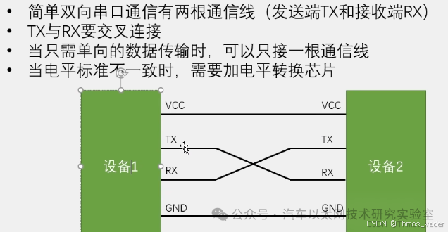
Frame Format
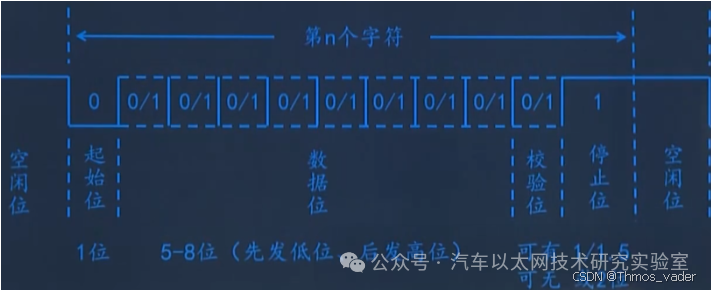
Timing
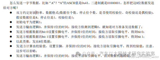
Baud rate:
Typically, baud rates of 9600, 19200, 115200, etc., are selected. This means the number of bits transmitted per second;
Start bit:
A logical “0” signal is sent first, indicating the start of data transmission;
Data bits:
Can be 5-8 bits of logical “0” or “1”, transmitting bit 0 first, then bit 1, and so on;
Parity bit:
After adding this bit to the data bits, the number of “1” bits should be even (even parity) or odd (odd parity) to check the correctness of data transmission.
The parity bit is optional and may not be transmitted;
Stop bit:
It is a character data end marker, and the data line returns to logical “1”;
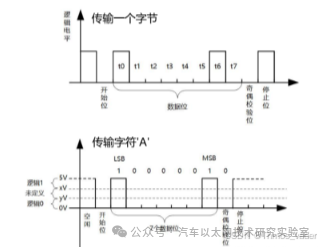
Sending a byte
Advantages and Disadvantages of USART
Advantages:
Communication requires only two data lines;
No clock signal is needed;
Parity bits are available for error checking in communication;
As long as the receiver and sender set up the data packet structure, stable communication can be achieved;
Disadvantages:
Lower transmission rate:
Data frames support a maximum of 9 data bits.
Electrical interfaces are not standardized:
UART communication generally uses the processor’s level, i.e., TTL level, but different processors have different levels (3.3V or 1.8V, or CMOS level).
Therefore, UARTs of different processors cannot be directly connected. Additionally, there is no unified interface for different devices, making hardware connections inconvenient.
Poor anti-interference capability:
Using TTL levels to represent 1 and 0, errors are likely to occur during transmission.
Short communication distance:
Generally only used for communication between two chips on a single circuit board.
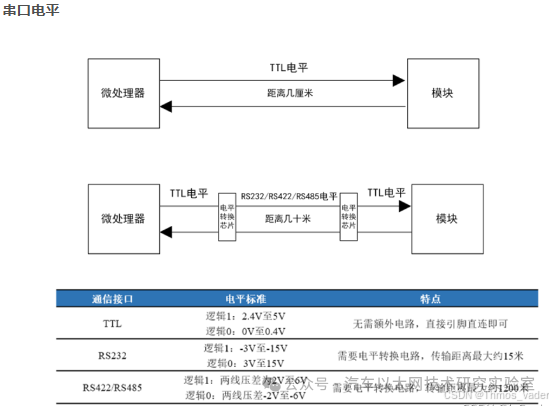
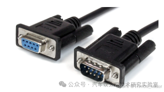
RS232
Interface Standard
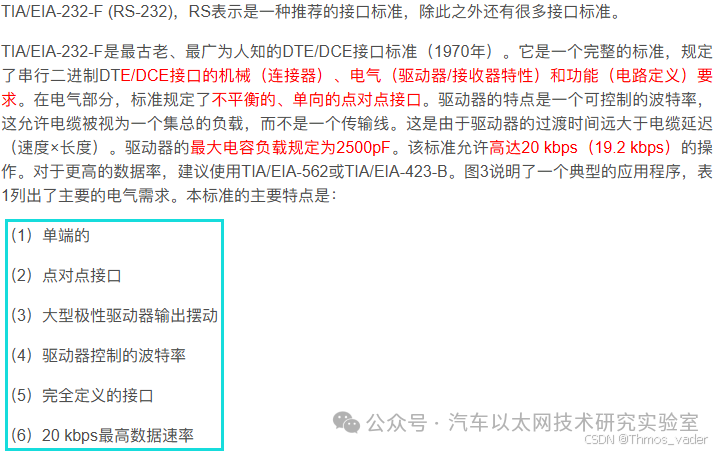
Voltage Level Standard
Transmission signal voltage levels (important):
-
+5 to +15 V represents 1, 5 to -15 V represents 0.
-
Receiving signal voltage levels:
Binary 0: +3 to +32 Vdc, Binary 1: -3 to -30 Vdc.
-
Relies on the UART serial port protocol, processing at the electrical level, standardizing the interface (as below), allowing for longer and faster transmission.
-
The signal sent by the MCU through TTL needs to connect to a level conversion chip to convert to RS232 signals, such as the MAX232 chip. Similar to USB-TTL chips (CH340, CP2302).
Characteristics
-
Increased anti-interference capability, communication distance approximately 15m.
-
Data format as follows:
Start bit: binary 0, Data: 5, 6, 7, or 8 bits.
Parity: odd, even, mark, or space (not applicable for 8-bit data).
Stop bit: binary 1, one or two bits.
Issues with RS232
-
The signal voltage levels of the interface are relatively high, which can damage the interface circuit chips;
-
Incompatible with TTL levels, so a level conversion chip is needed to connect with TTL circuits.
-
Lower communication speed, prone to common-mode interference, weak noise immunity, and shorter transmission distance (15m).
RS485 (Differential Signal Output, Half-Duplex)
Advantages of RS485
-
Lower interface voltage levels, less likely to damage interface circuit chips, and compatible with TTL levels. Can be easily connected to TTL circuits;
-
Fast communication speed.
-
Strong anti-noise interference capability.
-
Longer transmission distance (1500m).
-
Supports multi-node networking.
Interface Standard
Voltage Level Standard
-
Voltage level standard: differential +2V to +6V represents 1, -2V to -6V represents 0.
-
Connect a TTL to RS485 chip (single-ended to differential) after the MCU, such as MAX485.
Characteristics: Differential signal output, half-duplex.
-
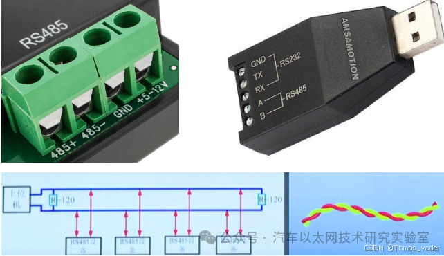
Communication uses twisted pair cables, differential signals, strong anti-interference.
-
Before sending, the single-ended signal is converted to a differential signal by the RS485 transceiver, then transmitted on the bus;
-
Similarly, before receiving, the differential signal on the bus is converted back to a single-ended signal by the transceiver and sent to the UART controller for reception;
-
Uses a two-wire system; since differential signals are used, two wires represent one signal, allowing only half-duplex communication. Does it feel similar to I2C? Only I2C specifies how the master manages the slave, while programming RS485 can completely mimic the master-slave logic of I2C to avoid conflicts.
-
If full-duplex bidirectional communication is desired on the RS485 bus, two pairs of differential signal lines (i.e., four signal lines) are needed. If only half-duplex bidirectional communication is required, only one pair of differential signals is needed;




*Disclaimer: This article is original or forwarded by the author.If it inadvertently infringes on someone’s intellectual property, please inform us for deletion.The above images and text are sourced from the internet; if there is any infringement, please contact us promptly, and we will delete it within 24 hours.The content of the article reflects the author’s personal views,and the Automotive Ethernet Technology Research Laboratory reprints it only to convey a different perspective, not representingthe Automotive Ethernet Technology Research Laboratory’s endorsement or support of this view. If there are any objections, please feel free to contact the Automotive Ethernet Technology Research Laboratory.
Original link:
https://blog.csdn.net/Thmos_vader/article/details/141197908