The SCADA group is used to bridge physical and virtual ports. The physical port, RS-232 serial port, connects to the local control center, while the virtual port, Virtual-Serial, transmits services to the remote terminal unit through PW. Within the SCADA group, it supports data broadcasting from the physical port to multiple virtual ports, and the data from multiple virtual ports is merged and filtered back to the physical port, thus achieving point-to-multipoint functionality.
Applicable Products and Versions
Applicable to NE05E&08E series routers of version V300R003C10 and later.
Networking Requirements
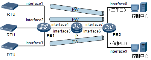
As shown in the figure below, each remote terminal unit has a PW for service transmission to the control center. The PE does not parse the service data; instead, the information from the control center is sent to the remote terminal units via broadcasting. When the remote terminal unit sends a response, only one PW is allowed to transmit the response information at the same time, while other PWs transmit idle information.
Figure 1-1 TDMoPSN Network Configuration Diagram

In this example, interface1, interface2, interface3, interface4, interface5, interface6, interface7, interface8, interface9 represent Serial0/4/1, Serial0/4/2, Serial0/4/3, GE0/1/4, GE0/1/5, GE0/1/6, GE0/1/7, Serial0/4/4, Serial0/4/5 respectively.
|
Device |
Interface |
IP Address |
|
PE1 |
GE0/1/4 Loopback0 |
10.1.1.1/24 192.168.1.1/32 |
|
P |
GE0/1/5 GE0/1/6 Loopback0 |
10.1.1.2/24 10.2.1.1/24 192.168.4.4/32 |
|
PE2 |
GE0/1/7 Loopback0 |
10.2.1.2/24 192.168.2.2/32 |
Configuration Steps
To configure a PW tunnel for TDM services in the PSN network, follow the steps below:
-
Run the IGP routing protocol on the backbone network so that all devices can communicate.
-
Configure MPLS basic capabilities on the backbone network and configure MPLS L2VPN on the PE devices. Establish an MPLS LDP remote peer relationship between the PEs at both ends of the PW.
-
Configure serial port attributes.
-
Configure TDM interface parameters.
-
Configure the SCADA group.
-
Configure PW.
-
Create MPLS L2VC connections on the PE.
Data Preparation
-
To complete this configuration example, prepare the following data:
-
L2VC ID for both ends of the PW (must be consistent)
-
Each PE and P’s MPLS LSR-ID
-
Set the IP address of the PE remote peer
-
Attributes of the RS-232 interface
Operational Steps
1. Run the IGP routing protocol on the backbone network to enable communication between devices (details omitted). For specific configurations, refer to the configuration file.
2. Configure MPLS basic capabilities on the backbone network and configure MPLS L2VPN on the PE devices. Establish an MPLS LDP remote peer relationship between the PEs at both ends of the PW (details omitted). For specific configurations, refer to the configuration file.

Establishing a dynamic PW requires setting up an MPLS LDP remote peer relationship.
3. Configure the RS-232 interface attributes, with a rate of 19200 bit/s.
a. Configure PE1.
# Configure the attributes of Serial 0/4/1, Serial 0/4/2, Serial 0/4/3 interfaces on PE1.
<HUAWEI> system-view
[~HUAWEI] sysname PE1
[*HUAWEI] commit
[~PE1] interface serial0/4/1
[~PE1-Serial0/4/1] portmode rs-232
[*PE1-Serial0/4/1] baudrate 19200
[*PE1-Serial0/4/1] databits 7
[*PE1-Serial0/4/1] stopbits 2
[*PE1-Serial0/4/1] parity odd
[*PE1-Serial0/4/1] mux-protocol 2
[*PE1-Serial0/4/1] x-50 set phasemode interval
[*PE1-Serial0/4/1] quit
[*PE1] commit
[~PE1] interface serial0/4/2
[~PE1-Serial0/4/2] portmode rs-232
[*PE1-Serial0/4/2] baudrate 19200
[*PE1-Serial0/4/2] databits 7
[*PE1-Serial0/4/2] stopbits 2
[*PE1-Serial0/4/2] parity odd
[*PE1-Serial0/4/2] mux-protocol 2
[*PE1-Serial0/4/2] x-50 set phasemode interval
[*PE1-Serial0/4/2] quit
[*PE1] commit
[~PE1] interface serial0/4/3
[~PE1-Serial0/4/3] portmode rs-232
[*PE1-Serial0/4/3] baudrate 19200
[*PE1-Serial0/4/3] databits 7
[*PE1-Serial0/4/3] stopbits 2
[*PE1-Serial0/4/3] parity odd
[*PE1-Serial0/4/3] mux-protocol 2
[*PE1-Serial0/4/3] x-50 set phasemode interval
[*PE1-Serial0/4/3] quit
[*PE1] commit
b. Configure PE2.
# Configure the attributes of Serial 0/4/4, Serial 0/4/5 interfaces on PE2.
<HUAWEI> system-view
[~HUAWEI] sysname PE2
[*HUAWEI] commit
[~PE2] interface serial0/4/4
[~PE2-Serial0/4/4] portmode rs-232
[*PE2-Serial0/4/4] baudrate 19200
[*PE2-Serial0/4/4] databits 7
[*PE2-Serial0/4/4] stopbits 2
[*PE2-Serial0/4/4] parity odd
[*PE2-Serial0/4/4] mux-protocol 2
[*PE2-Serial0/4/4] x-50 set phasemode interval
[*PE2-Serial0/4/4] quit
[*PE2] commit
[~PE2] interface serial0/4/5
[~PE2-Serial0/4/5] portmode rs-232
[*PE2-Serial0/4/5] baudrate 19200
[*PE2-Serial0/4/5] databits 8
[*PE2-Serial0/4/5] stopbits 1
[*PE2-Serial0/4/5] parity odd
[*PE2-Serial0/4/5] mux-protocol 0
[*PE2-Serial0/4/5] x-50 set phasemode interval
[*PE2-Serial0/4/5] quit
[*PE2] commit
4. Configure the encapsulation protocol of the serial port as TDM
a. Configure PE1.
# Set the encapsulation protocol to TDM for Serial 0/4/1, Serial 0/4/2, Serial 0/4/3 interfaces on PE1.
[~PE1] interface serial0/4/1
[~PE1-Serial0/4/1] link-protocol tdm
[*PE1-Serial0/4/1] quit
[*PE1] commit
[~PE1] interface serial0/4/2
[~PE1-Serial0/4/2] link-protocol tdm
[*PE1-Serial0/4/2] quit
[*PE1] commit
[~PE1] interface serial0/4/3
[~PE1-Serial0/4/3] link-protocol tdm
[*PE1-Serial0/4/3] quit
[*PE1] commit
b. Configure PE2.
# Create Virtual-Serial 0/4/1, Virtual-Serial 0/4/2, Virtual-Serial 0/4/0 interfaces on PE2 and set the encapsulation protocol to TDM.
[~PE2] interface virtual-serial0/4/1
[~PE2-Virtual-Serial0/4/1] link-protocol tdm
[*PE2-Virtual-Serial0/4/1] quit
[*PE2] commit
[~PE2] interface virtual-serial0/4/2
[~PE2-Virtual-Serial0/4/2] link-protocol tdm
[*PE2-Virtual-Serial0/4/2] quit
[*PE2] commit
[~PE2] interface virtual-serial0/4/0
[~PE2-Virtual-Serial0/4/0] link-protocol tdm
[*PE2-Virtual-Serial0/4/0] quit
[*PE2] commit
5. Create a SCADA group on PE2, adding the physical and virtual ports to the group to implement bridging.
[~PE2] scada-group 1
[*PE2-scada-group-1] commit
[~PE2-scada-group-1] quit
[~PE2] interface serial0/4/4
[~PE2-Serial0/4/4] scada-group 1 work
[*PE2-Serial0/4/4] commit
[~PE2-Serial0/4/4] quit
[~PE2] interface serial0/4/5
[~PE2-Serial0/4/5] scada-group 1 protect
[*PE2-Serial0/4/5] commit
[~PE2-Serial0/4/5] quit
[~PE2] interface virtual-serial0/4/1
[~PE2-Virtual-Serial0/4/1] bind scada-group 1
[*PE2-Virtual-Serial0/4/1] commit
[~PE2-Virtual-Serial0/4/1] quit
[~PE2] interface virtual-serial0/4/2
[~PE2-Virtual-Serial0/4/2] bind scada-group 1
[*PE2-Virtual-Serial0/4/2] commit
[~PE2-Virtual-Serial0/4/2] quit
[~PE2] interface virtual-serial0/4/0
[~PE2-Virtual-Serial0/4/0] bind scada-group 1
[*PE2-Virtual-Serial0/4/0] commit
[~PE2-Virtual-Serial0/4/0] quit
6. Configure PW
a. Configure PE1.
[~PE1] pw-template pe1tope2
[*PE1-pw-template-pe1tope2] peer-address 192.168.2.2
[*PE1-pw-template-pe1tope2] jitter-buffer depth 6
[*PE1-pw-template-pe1tope2] tdm-encapsulation-number 24
[*PE1-pw-template-pe1tope2] commit
[~PE1-pw-template-pe1tope2] quit
[~PE1] interface serial0/4/1
[~PE1-Serial0/4/1] mpls l2vc pw-template pe1tope2 101 control-word
[*PE1-Serial0/4/1] undoshutdown
[*PE1-Serial0/4/1] quit
[*PE1] commit
[~PE1] interface serial0/4/2
[~PE1-Serial0/4/2] mpls l2vc pw-template pe1tope2 102 control-word
[*PE1-Serial0/4/2] undoshutdown
[*PE1-Serial0/4/2] quit
[*PE1] commit
[~PE1] interface serial0/4/3
[~PE1-Serial0/4/3] mpls l2vc pw-template pe1tope2 103 control-word
[*PE1-Serial0/4/3] undoshutdown
[*PE1-Serial0/4/3] quit
[*PE1] commit
b. Configure PE2.
[~PE2] pw-template pe2tope1
[~PE2-pw-template-pe2tope1] peer-address 192.168.1.1
[*PE2-pw-template-pe2tope1] jitter-buffer depth 6
[*PE2-pw-template-pe2tope1] tdm-encapsulation-number 24
[*PE2-pw-template-pe2tope1] quit
[*PE2] commit
[~PE2] interface virtual-serial0/4/1
[~PE2-Virtual-Serial0/4/1] mpls l2vc pw-template pe2tope1 101 control-word
[*PE2-Virtual-Serial0/4/1] undo shutdown
[*PE2-Virtual-Serial0/4/1] quit
[*PE2] commit
[~PE2] interface virtual-serial0/4/2
[~PE2-Virtual-Serial0/4/2] mpls l2vc pw-template pe2tope1 102 control-word
[*PE2-Virtual-Serial0/4/2] undo shutdown
[*PE2-Virtual-Serial0/4/2] quit
[*PE2] commit
[~PE2] interface virtual-serial0/4/0
[~PE2-Virtual-Serial0/4/0] mpls l2vc pw-template pe2tope1 103 control-word
[*PE2-Virtual-Serial0/4/0] undo shutdown
[*PE2-Virtual-Serial0/4/0] quit
[*PE2] commit
7. Check the configuration results
Execute the command display mpls l2vc on the PE to check the status of the PW, which should be Up.
# Display on PE2.
<PE2> display mpls l2vc interface virtual-serial0/4/1
*client interface : Virtual-Serial0/4/1 is up
Administrator PW : no
session state : up
AC state : up
VC state : up
Label state : 0
Token state : 0
VC ID : 100
VC type : CESoPSN basic mode
destination : 192.168.1.1
local group ID : 0 remote group ID : 0
local VC label : 17 remote VC label : 17
local TDM Encap Num : 24 remote TDM Encap Num : 24
jitter-buffer : 6
idle-code : ff
local rtp-header : enable remote rtp-header : enable
local bit-rate : enable remote bit-rate : enable
local AC OAM State : up
local PSN OAM State : up
local forwarding state : forwarding
local status code : 0x0
BFD for PW : unavailable
VCCV State : up
manual fault : not set
active state : active
forwarding entry : exist
OAM Protocol : —
OAM Status : —
OAM Fault Type : —
PW APS ID : 0
PW APS Status : —
TTL Value : 1
link state : up
local VC MTU : 1500 remote VC MTU : 20000
local VCCV : cw alert ttl lsp-ping bfd
remote VCCV : cw alert ttl lsp-ping bfd
local control word : enable remote control word : enable
tunnel policy name : —
PW template name : pe2tope1
primary or secondary : primary
load balance type : flow
Access-port : false
Switchover Flag : false
VC tunnel/token info : 1 tunnels/tokens
Backup TNL type : lsp , TNL ID : 0x0
create time : 0 days, 18 hours, 36 minutes, 29 seconds
up time : 0 days, 0 hours, 0 minutes, 32 seconds
last change time : 0 days, 0 hours, 0 minutes, 32 seconds
VC last up time : 2014/11/11 10:36:45
VC total up time : 0 days, 1 hours, 25 minutes, 31 seconds
CKey : 2
NKey : 1
PW redundancy mode : frr
AdminPw interface : —
AdminPw link state : —
Diffserv Mode : pipe
Service Class : ef
Color : green
DomainId : —
Domain Name : —