1. Overview
CAN FD: It can be understood as an upgraded version of the CAN protocol, with only the protocol upgraded while the physical layer remains unchanged.
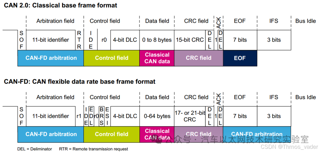
The main differences between CAN and CAN FD are: transmission rate, data length, frame format, and ID length.
2. CAN FD
The introduction of CAN FD (CAN with Flexible Data rate) is aimed at overcoming the limitations of traditional CAN bus in terms of data volume and speed.
The following are the limitations of the CAN bus and the improvements made by CAN FD:
2.1 Limitations of the CAN Bus
-
Limited data transmission bandwidth: Each frame of CAN 2.0 has only 8 bytes of data, with a maximum data rate of 1 Mbit/s. The rate commonly used in vehicles is 500 kbit/s. As the number of electronic control units (ECUs) in vehicles increases, frequent data interactions lead to an increasing bus load.
-
Low bandwidth utilization: In CAN messages, only about 40-50% of the bandwidth is used for actual data transmission, while the rest of the time is spent on message control and error detection. This results in low communication efficiency in applications with large data volumes.
-
Response mechanism delay: Due to the physical characteristics of automotive wiring, the response speed of the CAN bus is limited by various factors, including ACK confirmation delays in the controller, propagation delays in the transceiver, and transmission delays in the wires themselves.
2.2 Improvements of CAN FD
The CAN FD protocol began development in 2011 and was incorporated into the ISO 11898-1 standard in 2015. Its main improvements include:
-
Increased data segment length: CAN FD supports up to 64 bytes of data per frame, compared to the traditional CAN’s 8 bytes, significantly increasing the amount of effective data transmitted in a single transmission.
-
Dynamic data rate: CAN FD allows different bit rates to be used within the data frame. The message header maintains the original rate to ensure compatibility with traditional CAN; higher rates can be used in the data segment and CRC portion, enabling faster data transmission.
-
Reduced latency and improved bandwidth utilization: CAN FD optimizes frame structure and error detection mechanisms, enhancing bandwidth utilization efficiency, thus providing more effective data transmission under the same bus load.
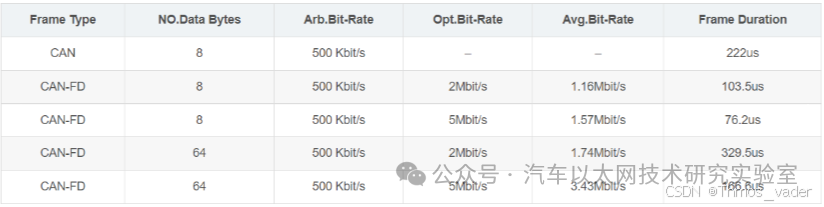
These improvements in CAN FD enable it to adapt to more complex automotive application scenarios, supporting greater data throughput and reducing bus load.
3. Protocol Similarities and Differences Between CAN FD and CAN 2.0
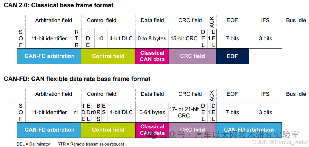
The following diagram visually compares CAN FD with CAN 2.0, and later we will focus on definitions, transmission rates, data lengths, frame formats, and ID lengths.
3.1 Different Definitions
CAN
-
Controller Area Network, i.e., a local area network for controllers;
-
CAN bus is one of the most widely used field buses internationally;
-
It has now become the standard bus for automotive computer control systems and embedded industrial control local area networks.
CAN-FD
-
In English, it is CAN with Flexible Data-Rate, translated as “Variable Rate CAN”;
-
It increases the transmission rate based on classic CAN, allowing the data field to transmit 64 bytes, which is the variable speed function, simply put, it is an upgraded version of CAN.
3.2 Different Transmission Rates
CAN
-
Maximum transmission rate of 1 Mbps.
CAN FD
-
Variable rate, with a maximum arbitration bit rate of 1 Mbps (same as CAN) and a maximum data bit rate of 8 Mbps, as shown in the following diagram:
3.3 Different Data Lengths
CAN
-
Maximum data length of 8 bytes per frame.
CAN FD
-
Maximum data length of 64 bytes per frame, mainly focusing on when DLC > 8.
-
CAN FD greatly expands the length of the data field:

3.4 Different Frame Formats
CAN FD
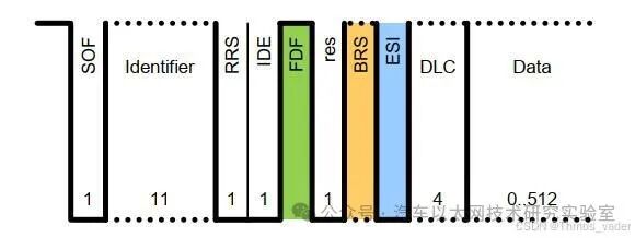
CAN FD introduces FDF, BRS, and ESI bits:
-
FDF: Indicates whether the message is a CAN or CAN-FD message.
-
BRS: Indicates bit rate switching; when this bit is dominant, the rate can vary (i.e., BSR to CRC uses the switching rate for transmission), and when this bit is recessive, it transmits at the normal CAN-FD bus rate (constant rate);
-
ESI: Indicates the status of the sending node.
3.5 Different ID Lengths
CAN
-
Standard frame ID length of up to 11 bits.
CAN FD
-
Standard frame ID length can be extended to 12 bits.
4. Analysis of CAN FD Frame Structure
-
CAN FD nodes can normally send and receive CAN messages, but CAN nodes cannot correctly send and receive CAN FD messages due to inconsistent frame formats.
-
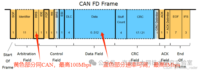
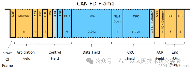
Like CAN, CAN FD consists of seven parts: frame start (SOF), arbitration segment, control segment, data field, CRC field, ACK field, and frame end.
The frame structure of CAN FD is as follows:
4.1 Frame Start
-
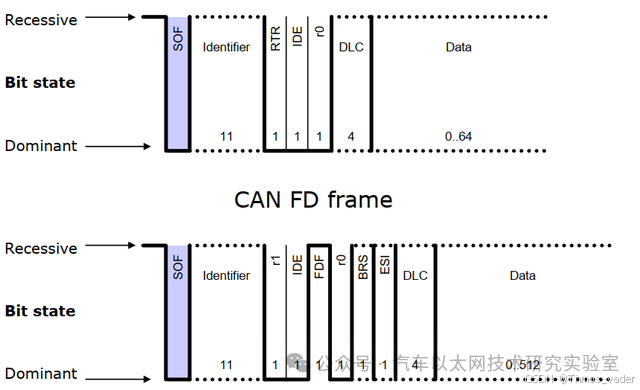
Both CAN and CAN FD use the same SOF flag bit to mark the start of the message.
-
The frame start consists of one dominant bit, marking the beginning of the message and serving a synchronization role on the bus.
4.2 Arbitration Domain
-
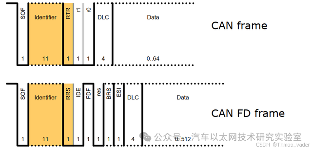
Unlike CAN, CAN FD removes support for remote frames, replacing the RTR bit with the RRS bit, which is always dominant.
-
IDE is used to distinguish between standard and extended frames.
4.3 Control Domain
-
CAN FD shares the same IDE, res, and DLC bits as CAN, while also adding three bits: FDF, BRS, and ESI. When FDF is recessive, it indicates a CAN FD message;
-
BRS is the rate switching control; when it is recessive, the rate can vary, and when it is dominant, it transmits at the normal CAN-FD bus rate (constant rate);
-
ESI indicates error status, with active errors sending a dominant bit and passive errors sending a recessive bit.
4.4 Data Domain
CAN FD is compatible with CAN’s data format, while also supporting a maximum of 12, 16, 20, 24, 32, 48, and 64 bytes.

4.5 CRC
-
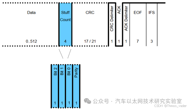
CAN FD has improved the CRC algorithm, including padding bits in the calculation.
-
In the checksum section, to avoid having more than six consecutive bits, it is determined to add a padding bit after the first bit and every four bits thereafter, with the value of the padding bit being the inverse of the previous bit, serving as a format check; if the padding bit is not the inverse of the previous bit, an error is processed.
-
The CRC field of CAN FD has been extended to 21 bits.
3.6 ACK
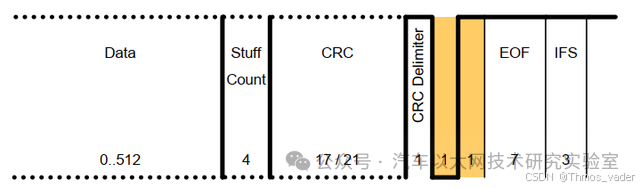
ACK follows the CRC end identifier.
In contrast, CAN FD supports 2 bits of ACK recognition.
3.7 Frame End
-
Like CAN, the frame end of CAN FD also consists of seven consecutive recessive bits.