Failure of PCB Through-Hole ICD: Analysis and Prevention of Inner Layer Interconnection Defects
As electronic products evolve towards higher density and reliability, ICD issues have increasingly become a key factor affecting PCB quality. The risk of ICD failure significantly increases, especially in high-frequency, high-speed materials, thick boards, and HDI boards. Understanding the mechanisms of ICD failure and implementing effective controls have become core competencies for PCB manufacturing enterprises.
01 Nature and Hazards of ICD Failure
ICD, short for Inner Connection Defects, specifically refers to reliability issues at the connection points between the inner layer copper and the hole copper in PCBs.
The uniqueness of these defects lies in their strong concealment. During the electrical testing process, the pressure from the test probes may temporarily maintain the connection, making it difficult to effectively intercept ICD issues, leading to defects flowing downstream or even to the client.
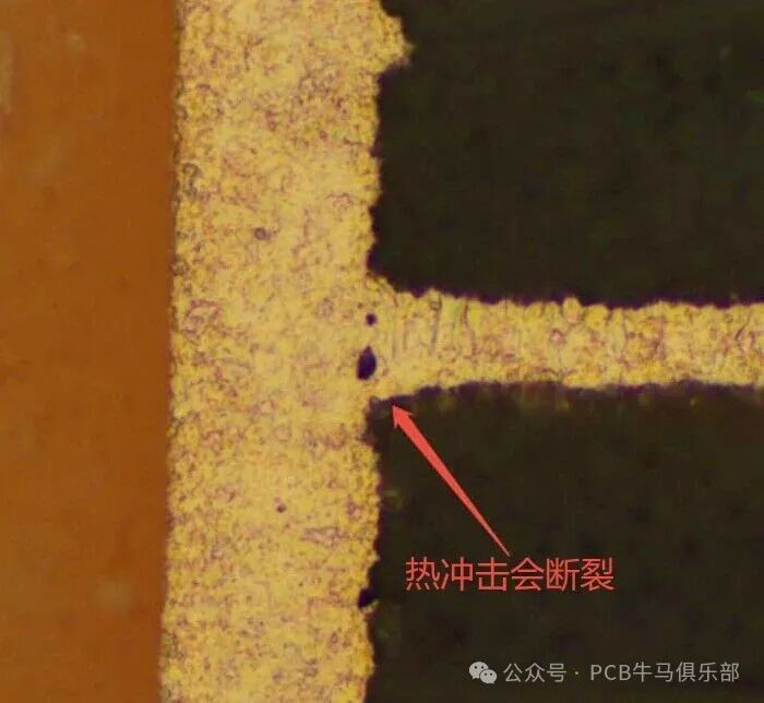
When PCBs undergo lead-free reflow soldering, wave soldering, and other high-temperature processes, thermal stress can cause micro-cracks at weak connection points, ultimately leading to open circuits. By this time, the PCB has already been assembled, and the resulting losses will multiply.
For high-frequency, high-speed circuits, aerospace, medical electronics, and other high-reliability application fields, ICD represents a significant quality risk and potential for market recalls.
02 Mechanisms of ICD Failure
1. Fragment-Based ICD
This type of ICD originates from debris left over during the drilling process. When the drill bit cuts through the PCB material, it generates chips, glass fiber fragments, and inorganic filler residues.
If the de-gluing process is not thorough, these residues can embed into the surface of the inner layer copper, forming interfacial contamination that weakens the bonding strength between copper layers.
For high-frequency, high-speed materials, due to the high resin filler content in the dielectric layer and their hard physical properties, the roughness of the hole walls during drilling is greater, making it easier to produce a large amount of debris.
2. Copper Bonding Failure ICD
Copper bonding failure is closely related to the mismatch in thermal expansion coefficients of materials. When the PCB undergoes high-temperature processes, the differences in the Z-axis expansion coefficients of different materials (resin, copper, glass fiber) can lead to interfacial stress.
The differences in crystalline structures between the electroless copper layer and the electroplated copper layer further exacerbate this phenomenon. Weak bonding areas can develop micro-cracks under thermal stress, ultimately leading to open connections.
In recent years, with the increase in PCB thickness and the rise in lead-free soldering temperatures, the incidence of copper bonding failure ICD has been on the rise.
3. Stress-Type ICD
This is a special type of copper bonding failure, primarily arising from internal stresses formed during the PCB processing. When the material is rigid or processing parameters are inappropriate, the drilling and plating processes can leave residual stress at the inner connection points.
These stresses can be released during subsequent high-temperature processes, leading to cracks at the connection points. Rigid-flex boards, due to their significant differences in material mechanical properties, are more prone to stress-type ICD.
03 Key Influencing Factors of ICD Failure
1. Material Factors
High-frequency, high-speed materials typically exhibit low Dk (dielectric constant) and low Df (dielectric loss) characteristics, with low polarity and low material activity, making de-gluing difficult.
Halogen-free materials, due to the substitution of P and N for halogens, reduce the polarity of polymer chains, leading to poor compatibility with standard electroplating solutions, which can easily cause thin plating issues.
The differences in thermal expansion coefficients (CTE) of different materials are also a key factor. When multilayer boards are pressed with different materials, the differences in Z-axis expansion coefficients can significantly increase the risk of ICD.
2. Drilling Quality
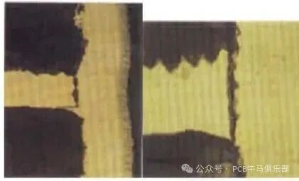
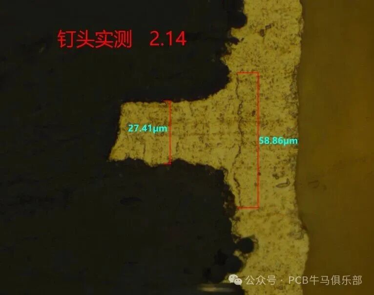
The quality of drilling directly affects ICD. High roughness of hole walls and abnormal nail heads can lead to poor circulation of de-gluing solutions, resulting in inadequate de-gluing effects.
The wear condition of the drill bit is also important. As the number of uses increases, the quality of the hole walls can significantly decline, increasing the risk of residual glue.
For flexible materials such as polyimide (PI) and high-frequency materials like Teflon (PTFE), poor machinability and large deformation make it easier to generate nail heads and stress concentration.
3. De-gluing Process
Inadequate de-gluing is one of the main causes of ICD. In the chemical de-gluing process, insufficient potassium permanganate concentration or inadequate treatment time can lead to resin glue residues.
For high-frequency materials and high aspect ratio holes, traditional chemical de-gluing may not be sufficient to ensure complete removal of residual glue. More advanced de-gluing technologies, such as plasma treatment, are required.
04 Detection and Analysis Methods for ICD Failure
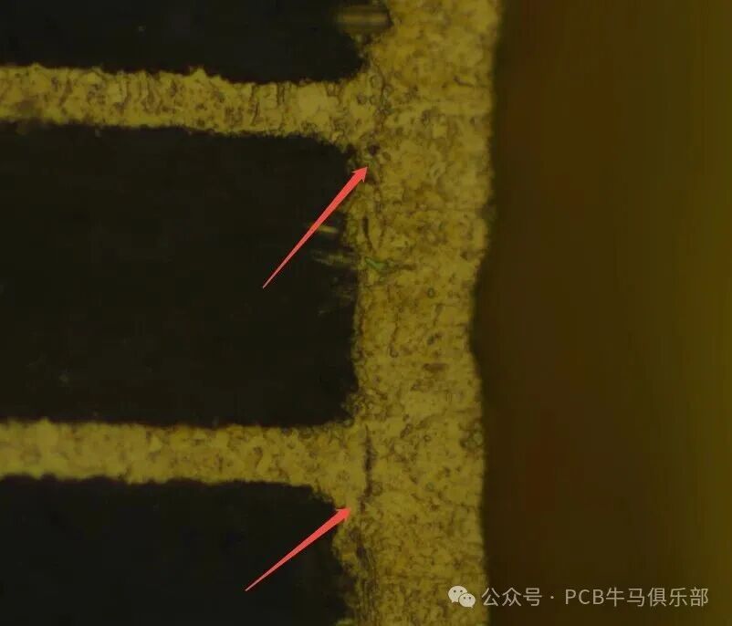
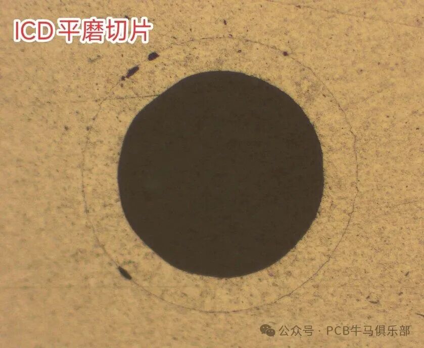
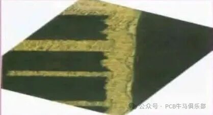
1. Cross-Sectional Analysis
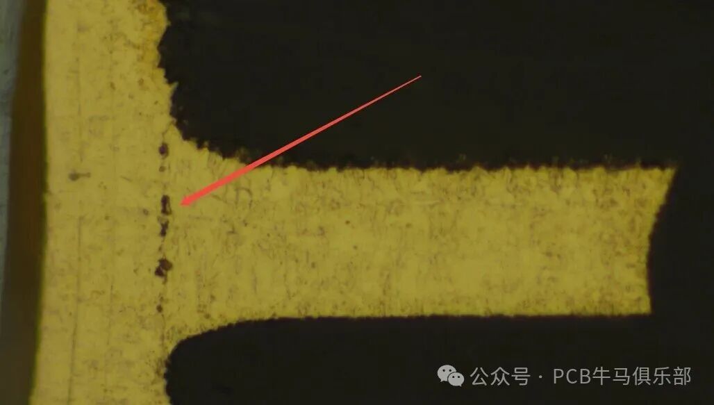
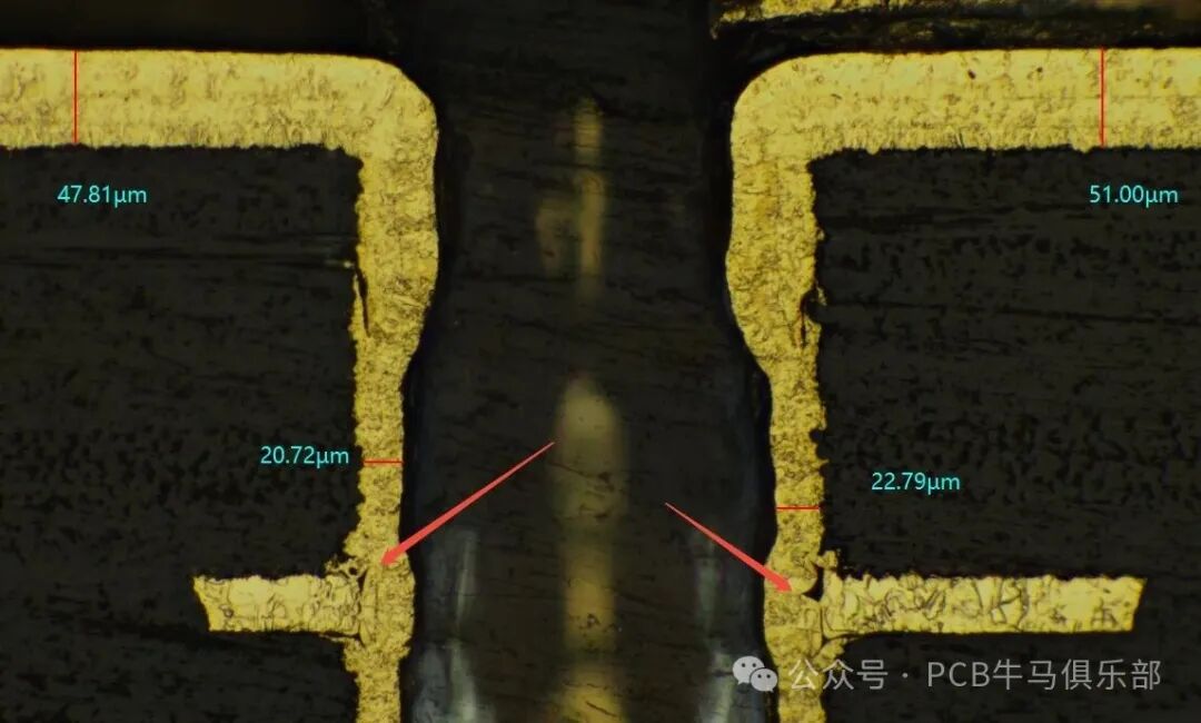
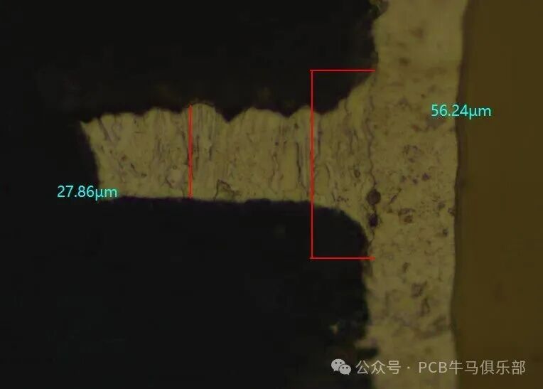
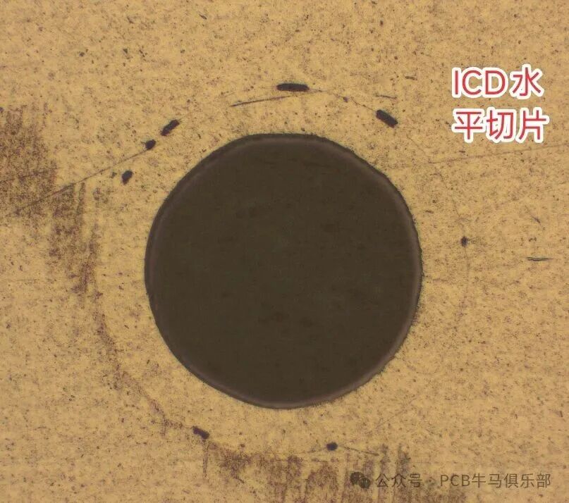
Cross-sectional analysis is a classic method for detecting ICD. By preparing cross-sectional slices of the PCB and observing the interfacial conditions at the inner connections under a microscope, residual glue, micro-cracks, and other defects can be visually identified.
2. 3D Microscopy and FIB Analysis
Advanced analytical methods such as 3D microscopy and Focused Ion Beam (FIB) can more precisely define the types and mechanisms of ICD, especially important for analyzing stress-type ICD.
3. Thermal Stress Testing
Thermal stress testing is an effective method for assessing ICD reliability. By simulating high-temperature processes such as reflow soldering, potential defects can be accelerated to expose, thereby evaluating the PCB’s resistance to ICD.
05 Preventive and Control Measures for ICD Failure
1. Material Selection and Matching
When selecting high-frequency, high-speed materials, it is essential to consider parameters such as Tg (glass transition temperature), Td (thermal decomposition temperature), and thermal expansion coefficients.
For mixed-press structures, materials with matching CTE should be chosen to reduce differences in Z-axis thermal expansion.
2. Optimization of Drilling Parameters
Optimizing drilling parameters is key to improving hole wall quality. By controlling the number of stacked layers, drill bit wear, and cutting parameters, the roughness of hole walls and nail head phenomena can be significantly reduced.
Practical experiments have shown that appropriate parameter optimization can control hole wall roughness to below 15μm and nail heads to below 20μm, meeting high-quality requirements.
3. Advanced De-gluing Processes
For high-frequency, high-speed materials, a combination process of “plasma de-gluing + chemical de-gluing” can effectively solve the residual glue problem.
Plasma de-gluing, through physical bombardment, can remove stubborn residues that chemical solutions struggle to handle, especially suitable for high aspect ratio holes and special materials.
4. Process Innovation
The positive etching technology developed by leading companies, by controlling plasma parameters and glass fiber etching parameters, achieves positive etching of 2-5um, effectively burning off the contents at the connection, including dust and resin, thus preventing ICD failure. The inner layer copper that has been de-glued is protruding, indicating that the de-gluing is thorough. Such processes need to control hole wall roughness; excessive positive etching can lead to exceeding roughness standards.
5. Strict Process Monitoring
Establish a comprehensive process monitoring system, especially for the regular testing and replacement of de-gluing solution, ensuring the activity of the solution remains within effective ranges.
For high-frequency, high-speed boards, it is recommended to add inspection steps after de-gluing to ensure the quality of de-gluing meets requirements.
Looking to the future, integrating real-time monitoring intelligent drilling systems, big data-based process parameter optimization, and new interface-enhancing materials will be key paths for the PCB industry to tackle ICD challenges. Only companies that master the core technologies for ICD prevention and control can remain competitive in the high-end PCB market.
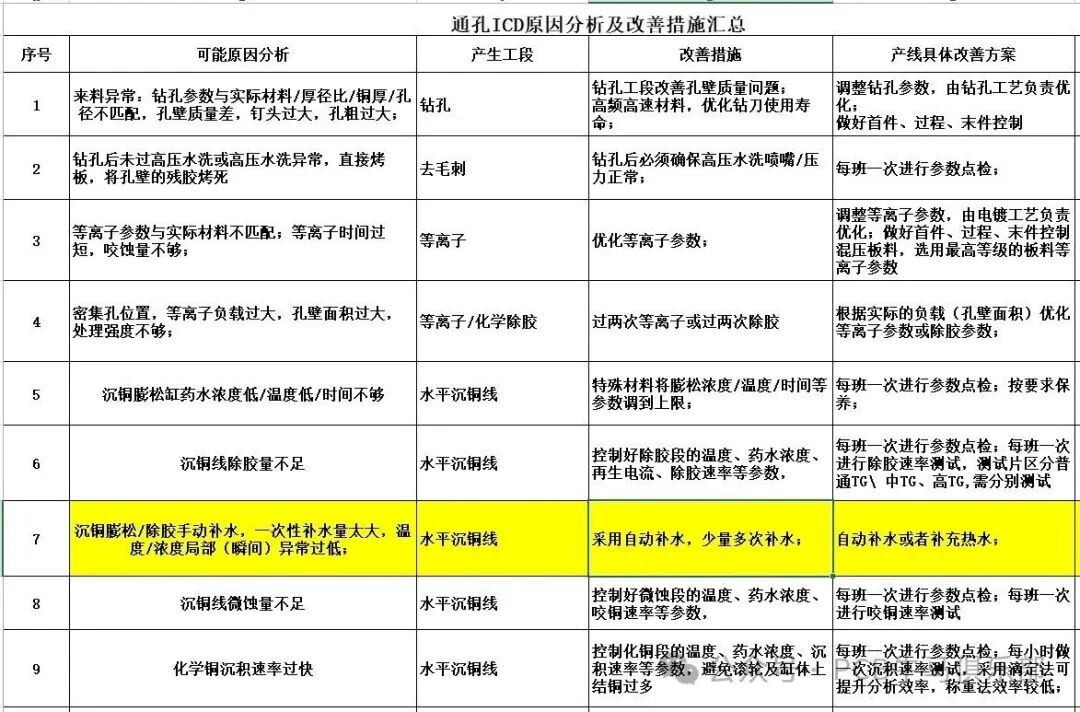
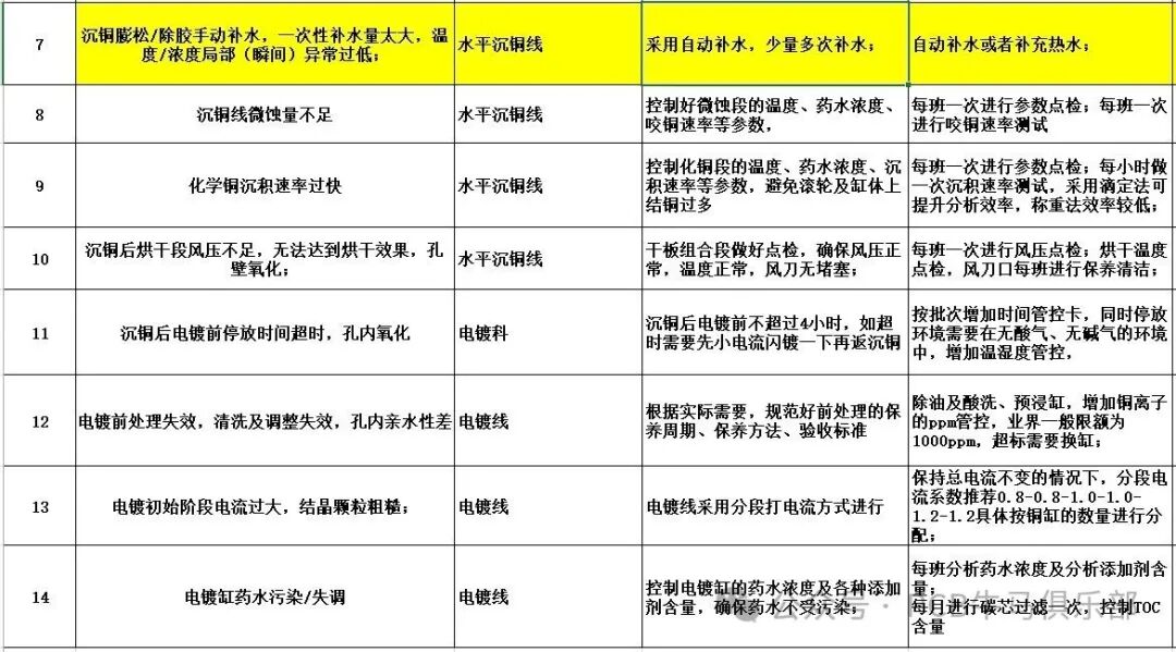
Attachment: Summary of Causes and Improvement Measures for Through-Hole ICD (Practical Insights)
 Special Note: The above discussion is for reference only and serves as a starting point for further exploration! Each factory’s solutions, processes, equipment, and product structures vary significantly, and one must not apply experiences rigidly. All effective improvement measures stem from experimental data! As a professional quality of engineering technicians, it is essential to “speak with data.”Source: Compiled from internet materials for the purpose of exchange and learning.
This public account will continue to update information related to PCB manufacturing and cutting-edge technologies. If you find it helpful, please follow, bookmark, share, and like!
Thank you, not only for being so good-looking and handsome but also for moving your golden fingers to help you prosper, please follow, bookmark, share, and like!!!
Original content is not easy; if you wish to reprint, please message the author for permission and indicate the source before reprinting. Thank you for your cooperation!