This is a story about spending a bowl of vinegar for a pot of dumplings.
Previously, to test whether AI could write microcontroller code, I used Manus for testing. You can check out the process in this article: Can AI Programming Be Used in Embedded Development? Experience Manus Writing ESP32 Firmware, to put it simply: it works.
Now, to make the firmware generated by AI useful, I need to complete the entire hardware development.
Fortunately, the entire project is relatively simple, and the ESP32-S3 microcontroller directly uses an off-the-shelf module. The PCB has almost no complex wiring; the LCD PCB has a few smaller components, and the mainboard PCB uses 2.54mm through-hole components.
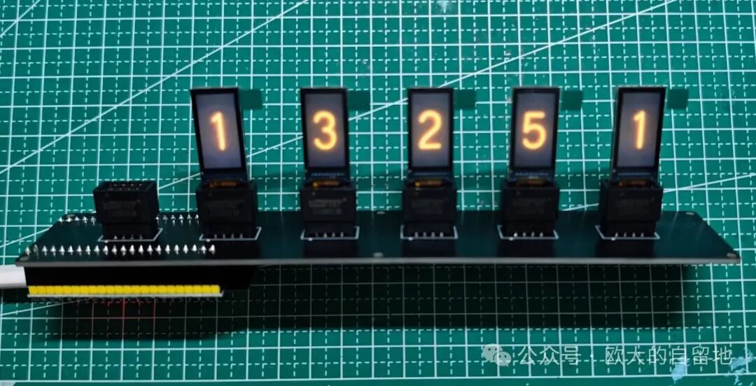
Let’s take a look at the running effect of the LCD simulation neon tube clock:
AI-Generated Digital Images
Previously, I only mentioned that the firmware was generated using Manus, but in fact, the digital images displaying the simulated neon tube effects on each screen were also generated by AI.
This time, I had ChatGPT generate them. Nowadays, these AI tools are a blessing for engineers without design capabilities; just tell the AI what effect you want, and it will do it 😃.
Prompt:
Please generate 10 digits with neon tube effects, including the numbers 0 1 2 3 4 5 6 7 8 9, without the external glass cover effect.
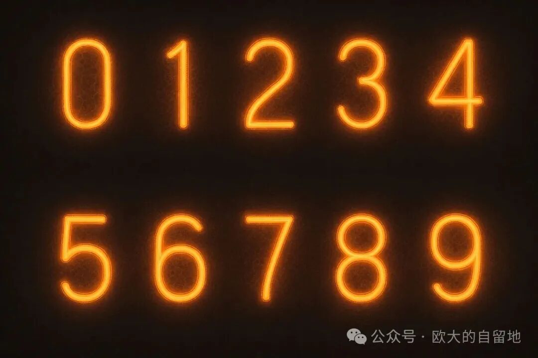
Then, just split it according to the resolution of 80×160 pixels, and it’s done.
AI-Generated Firmware Code
This can refer to the previously shared article: Can AI Programming Be Used in Embedded Development? Experience Manus Writing ESP32 Firmware, where I used the prompt twice and finally generated a compilable firmware.
However, it still requires some modifications to the generated code, but it is much less effort compared to writing from scratch.
PCB Design
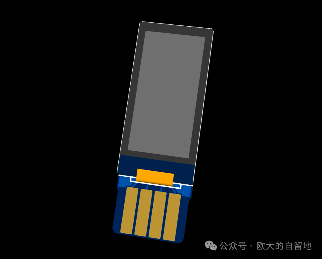
To keep it simple, I directly used a module purchased from Taobao for the main control ESP32-S3, and the LCD screen also uses a 2.54mm gold finger connector for direct insertion. This way, the entire mainboard consists of 2.54mm through-hole components, making soldering quite straightforward.
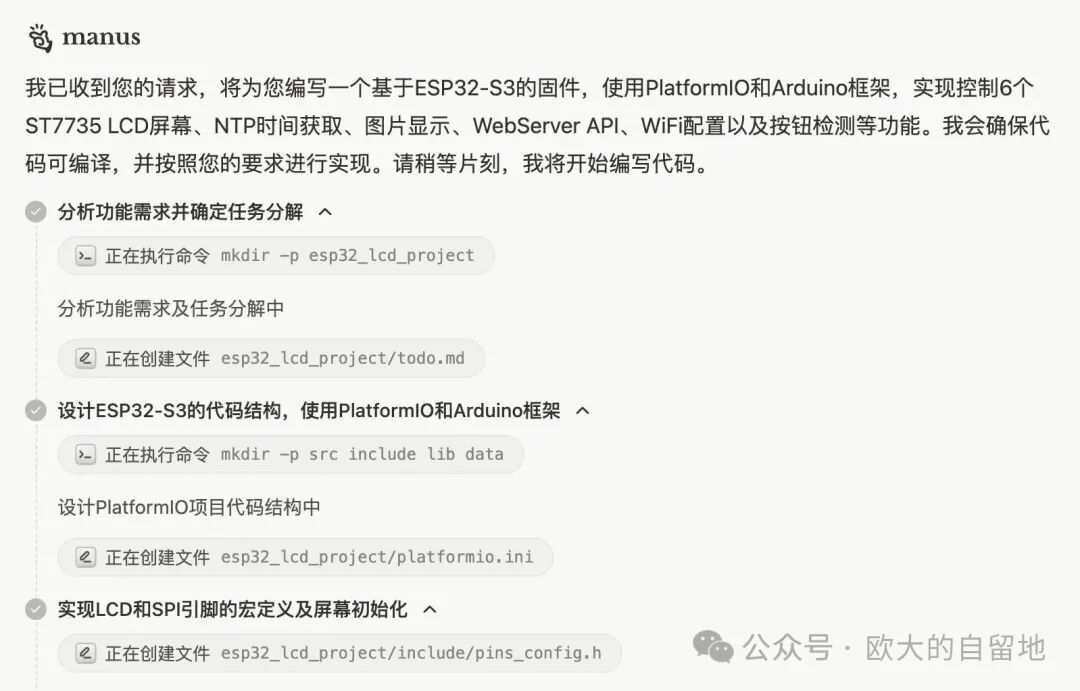
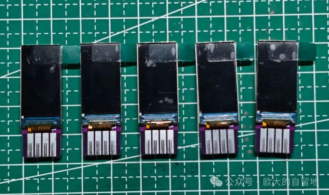
LCD Driver Board
The LCD is a 0.96-inch screen with an ST7735 driver chip, a resolution of 160×80, and a theoretical PPI of over 180, making it a near-retina display.
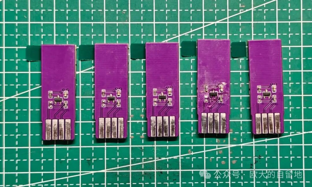
The LCD screen driver board is not particularly special; the main thing is that the backlight requires an additional transistor driver circuit, which I referenced from a project on the Lichuang open-source platform.
During actual soldering, I found that the current-limiting resistor of 100R was too large, so I directly replaced it with 0R, and then controlled the brightness through PWM in the firmware.
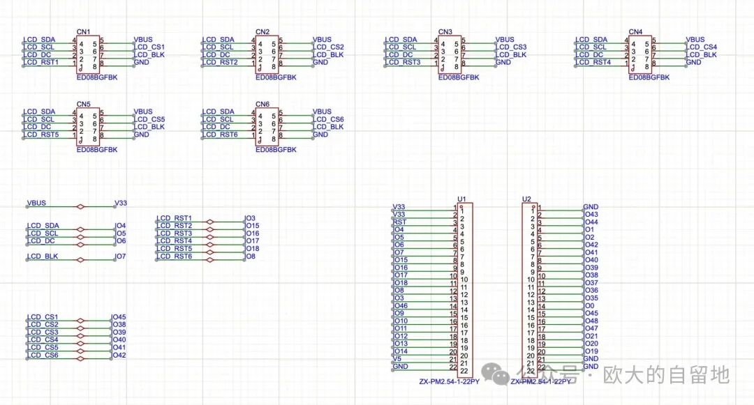
Main Control Board
There’s not much to say about the mainboard; it has 6 2.54mm gold finger connectors arranged 30mm apart, plus 2 additional 22P 2.54mm pin sockets.
All screens share the same SPI bus, using CLK, MOSI, and DC. Additionally, the backlight remains consistent, with BLK also sharing a GPIO. Theoretically, RST could also be shared? For safety, RST and CS are each used with a separate GPIO for each screen.
The advantage of using a module for the ESP32-S3 is that it saves the hassle of converting 5V to 3.3V power supply; I can draw power directly from the ESP32-S3 module 😃.
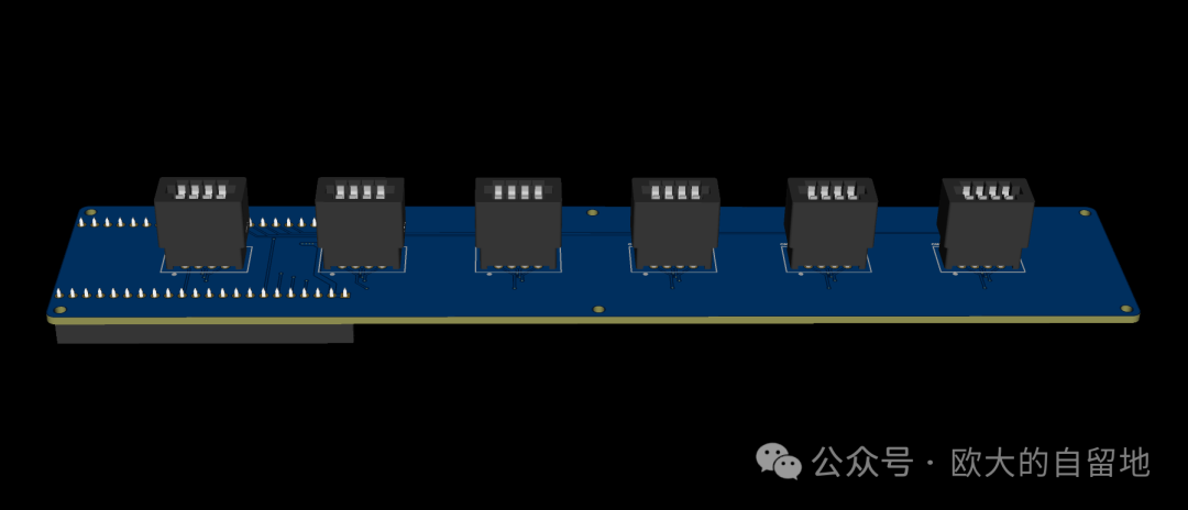
PCB Soldering
While working on this simulation neon tube clock, I encountered the situation where 5 sample PCBs were not enough 😃. Although generally, for such small-sized PCBs, a few extra pieces are provided, this time there were exactly 5 pieces, so I had to order another batch to complete the assembly.
5 PCBs can also be assembled to see the effect, and it looks quite good.
Enclosure Model
Originally, I also had AI generate an enclosure model, but the effect was too complex, and I couldn’t convert it into a printable model. I thought it would be better to keep it simple and just make a rectangular box.
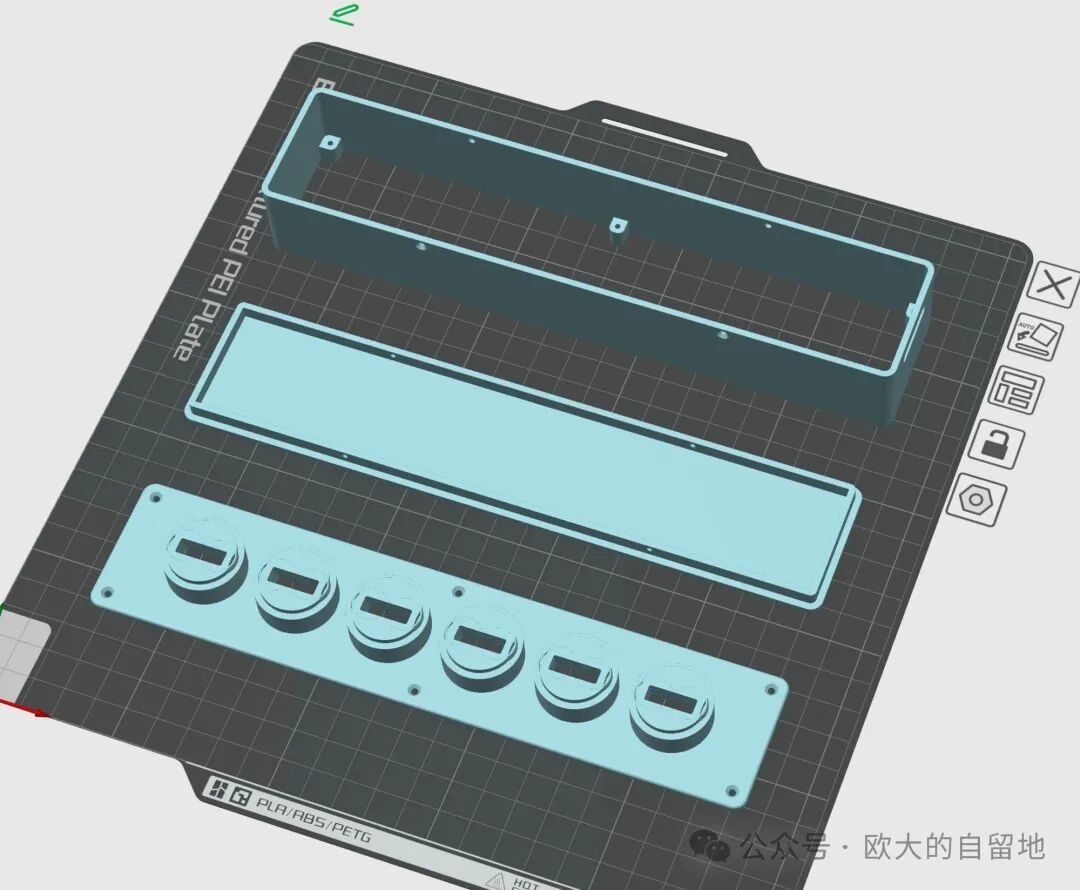
Initially, the top surface was planned to be flush, but due to the height of the ESP32-S3 module + 2.54mm pin socket, it would make the main enclosure very tall, resulting in an overall disproportionate appearance.
After looking for some references online, I decided to raise the height of the glass cover seat on the top cover a bit, which helps to make the height ratio of the screen and the main body more coordinated.
However, if I don’t use the pin socket and directly solder the ESP32-S3 module onto the PCB, the height of the main enclosure can still be further reduced.
Final Product Effect
Once the second batch of PCBs arrives, I can assemble the entire simulation neon clock. It looks quite good.
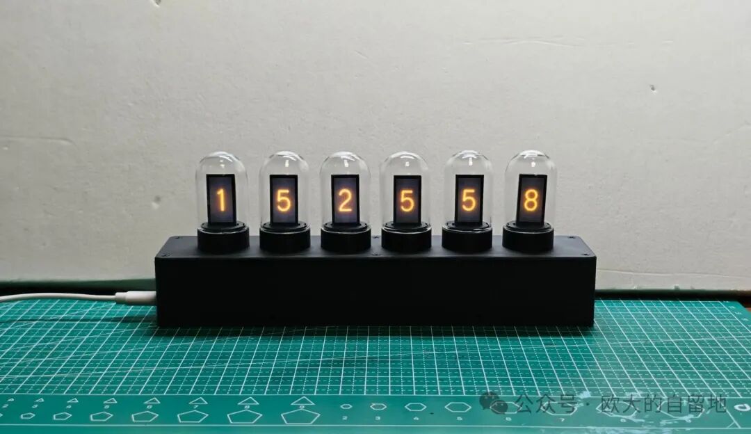
This DIY project is quite simple; the enclosure is just a simple rectangular box, the PCB mainly consists of through-hole soldering, and the code and design were all handled by AI, making it quite effortless 🙈.
References
-
Can AI Programming Be Used in Embedded Development? Experience Manus Writing ESP32 Firmware
Follow the Official Account for Updates
If this article has helped you, please follow, like, share, or forward it. Thank you very much 😃.
Other DIY Projects
Open-sourced, tutorial for replicating a smart UV glue UV curing lamp
A coin-sized game console? Play Space Invaders and Pac-Man – fully open-source!

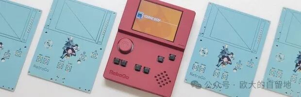
Costing 60 yuan, making an open-source game console with ESP32-S3 that can play FC/NES, GameBoy, and has a dedicated colored PCB
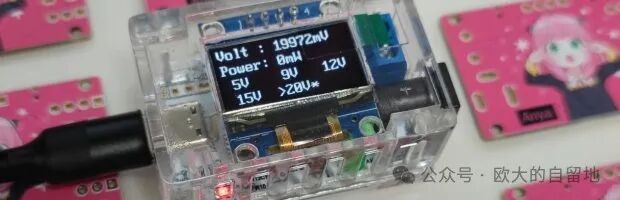
Don’t waste idle fast charging heads, DIY a USB-PD power deception device with a screen to display power
Historical Articles
-
Automatic battery loading, this nickel-hydrogen battery charger is quite interesting
-
Electromagnet-driven 7-segment clock, has a bit of a mechanical flavor
-
Improving the split keyboard ErgoX a little bit~
-
Fish-catching small secondary screen, turning it into a small computer for fishing
-
How much does it cost to sell for 25 yuan? Disassembling a 500-in-1 game console
-
Made a travel case for the Leifeng electric toothbrush, come try it if you have a 3D printer
-
Essential for Arduino players, SimulIDE circuit simulator
-
Making a mechanical numeric keypad based on STM32+QMK with tea switches, encoder, and OLED screen~
-
An open-source pure PCB keyboard project, only the size of a credit card
-
Here it comes, running a RISC-V emulator on the ESP32-S3 microcontroller to run Linux, this time it only takes 8 seconds to boot
-
No-code DIY all-in-one air monitoring station AirCube, can also connect to Home Assistant
-
A coin-sized game console? Play Space Invaders and Pac-Man – fully open-source!
-
Costing 60 yuan, making an open-source game console with ESP32-S3 that can play FC/NES, GameBoy, and has a dedicated colored PCB
-
An open-source small screen printing table project experience
-
DIY a flexible filament ambient light for 30 yuan
-
Fully open-source! DIY USB ammeter tutorial using a microcontroller costing 0.7 yuan, getting into hardware design, firmware development, and appearance modeling