System Overview
This design uses STM32CubeMX to configure the STM32F401CC, controlling the left motor direction via PB2/PB3, with PA1 providing PWM for the left motor; PB0/PB1 controls the right motor direction, with PA0 providing PWM for the right motor. The simulation of the TURTLE car is implemented in Proteus, receiving Bluetooth commands through serial communication.
STM32CubeMX Configuration
1. Pin Configuration
-
Left Motor Control:
-
PB2 – Direction 1 (GPIO Output)
-
PB3 – Direction 2 (GPIO Output)
-
PA1 – TIM2_CH2 (PWM Output)
-
Right Motor Control:
-
PB0 – Direction 1 (GPIO Output)
-
PB1 – Direction 2 (GPIO Output)
-
PA0 – TIM2_CH1 (PWM Output)
-
Serial Communication:
-
PA9 – USART1_TX
-
PA10 – USART1_RX
2. Clock Configuration
-
System Clock: 16MHz
-
APB1 Timer Clock: 16MHz
3. Timer Configuration (TIM2)
-
Channel 1: PWM Generation CH1 (PA0)
-
Channel 2: PWM Generation CH2 (PA1)
-
Prescaler: 15 (1MHz Clock)
-
Counter Period: 2000
4. USART Configuration
-
Baud Rate: 9600
-
Data Length: 8 bits
-
Stop Bits: 1
-
No Parity
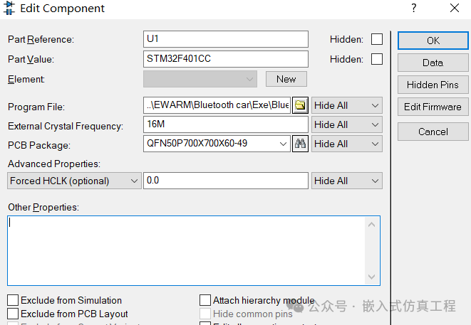
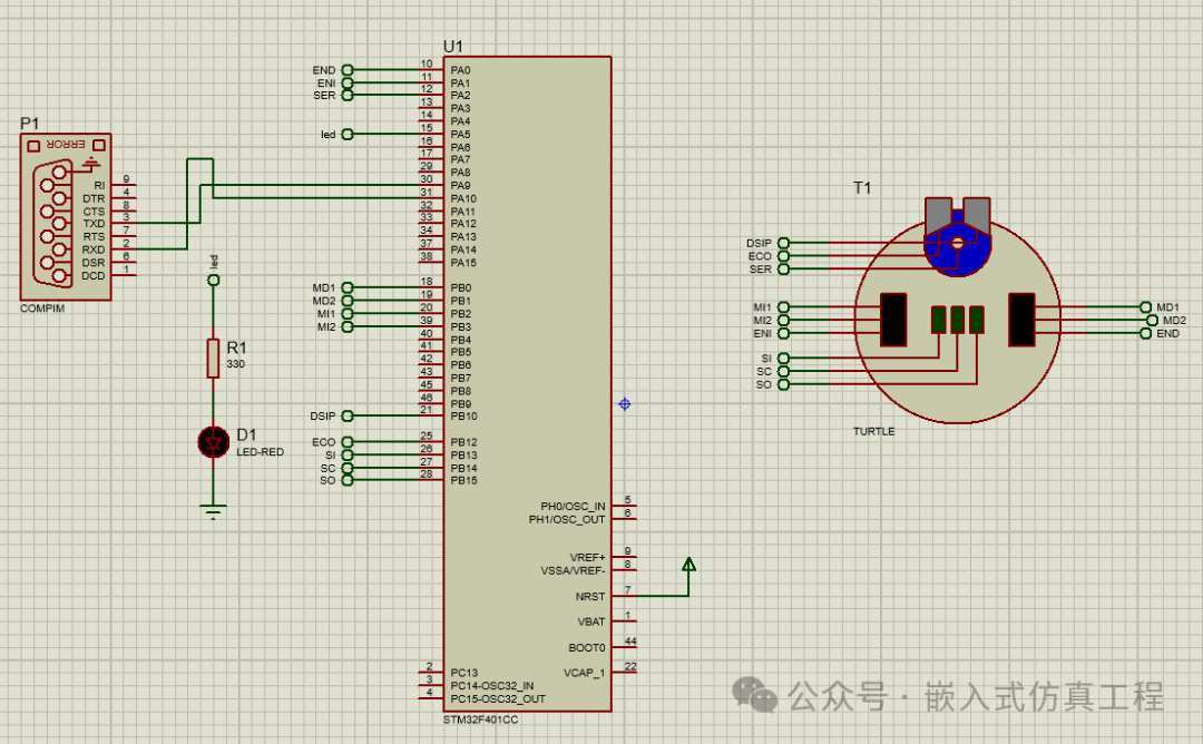
Proteus Circuit Design
1. Component List
-
STM32F401CC
-
TURTLE Module
-
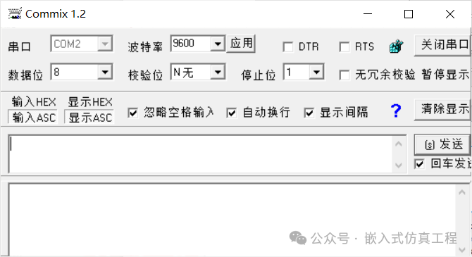
VIRTUAL TERMINAL
2. Circuit Connections
-
Left Motor Control:
-
PB2 → TURTLE Left Motor IN1
-
PB3 → TURTLE Left Motor IN2
-
PA1 → TURTLE Left Motor EN
Right Motor Control:
-
PB0 → TURTLE Right Motor IN1
-
PB1 → TURTLE Right Motor IN2
-
PA0 → TURTLE Right Motor EN
Serial Communication:
-
PA9 → VIRTUAL TERMINAL RXD
-
PA10 → VIRTUAL TERMINAL TXD
Generate the IAR project and write the application code, compiling to create an executable HEX file.
int main(void)
{
/* USER CODE BEGIN 1 */
/* USER CODE END 1 */
/* MCU Configuration——————————————————–*/
/* Reset of all peripherals, Initializes the Flash interface and the Systick. */
HAL_Init();
/* USER CODE BEGIN Init */
/* USER CODE END Init */
/* Configure the system clock */
SystemClock_Config();
/* USER CODE BEGIN SysInit */
/* USER CODE END SysInit */
/* Initialize all configured peripherals */
MX_GPIO_Init();
MX_DMA_Init();
MX_TIM2_Init();
MX_USART1_UART_Init();
/* USER CODE BEGIN 2 */
HAL_GPIO_WritePin(GPIOB, DSIP_Pin, 1);
HAL_GPIO_WritePin(GPIOB, ECO_Pin, 1);
HAL_GPIO_WritePin(GPIOB, SI_Pin, 1);
HAL_GPIO_WritePin(GPIOB, SC_Pin, 1);
HAL_GPIO_WritePin(GPIOB, SO_Pin, 1);
PWM_init(&PWMT2, PWM1_CH);
PWM_init(&PWMT2, PWM2_CH);
SERVO_init(&PWMT2, SERVO1_CH);
pwm_valor(&PWM1,100);
pwm_valor(&PWM2, 100);
SERVO_ANG(&SERVO1, 0);
memset(trama_rx,0,buff_RX);//
HAL_UARTEx_ReceiveToIdle_IT(&huart1, (uint8_t*)trama_rx, buff_RX);//
/* USER CODE END 2 */
/* Infinite loop */
/* USER CODE BEGIN WHILE */
while (1)
{
if(flag_rx==1){
procesarx();
flag_rx=0;
memset(trama_rx,0,buff_RX);
HAL_UARTEx_ReceiveToIdle_IT(&huart1, (uint8_t*)trama_rx, buff_RX);
}
uartx_write_text(&huart1, “Hola”);
HAL_GPIO_TogglePin(led_GPIO_Port, led_Pin);
HAL_Delay(200);
/* USER CODE END WHILE */
}
/* USER CODE END 3 */
}
Proteus Simulation Steps
-
Build the Circuit:
-
Left Motor IN1: PB2
-
Left Motor IN2: PB3
-
Left Motor EN: PA1
-
Right Motor IN1: PB0
-
Right Motor IN2: PB1
-
Right Motor EN: PA0
-
Build the complete circuit according to the above connections and load the HEX file generated by the project.
-
Configure the TURTLE module:
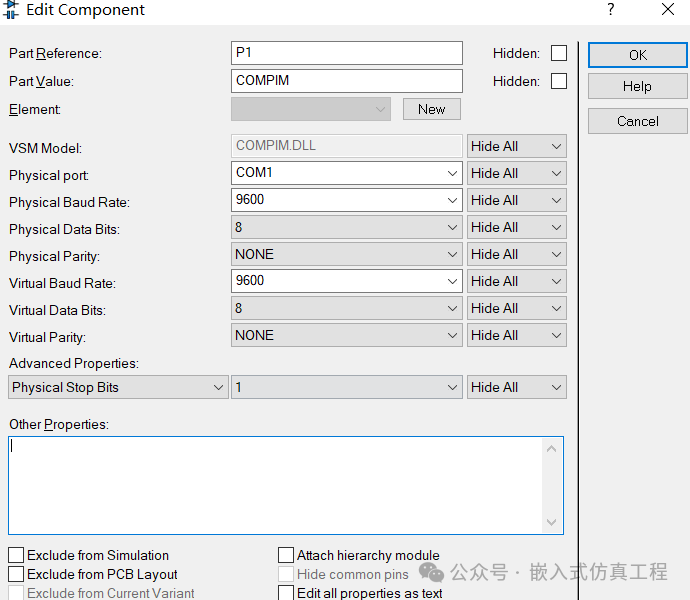
Configure the Virtual Terminal:
-
Baud Rate: 9600
-
Data Bits: 8
-
Stop Bits: 1
-
No Parity
-
Install the virtual serial port VSPD and create two virtual serial ports.
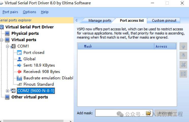
-
Configure the virtual serial port in Proteus.
-
Configure the debug serial port.
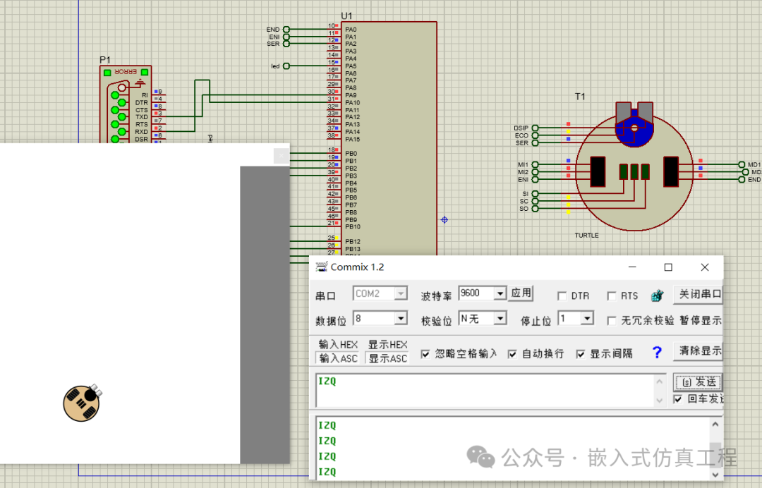
Simulation Operation:
-
ADEL: Move Forward
-
ATRA: Move Backward
-
IZQ: Turn Left
-
DER: Turn Right
-
STOP: Stop
-
Start the simulation.
-
Input control commands in the virtual terminal: ADEL, ATR, IZQ, DER, STOP, and observe the movement.
Debugging Tips
-
Motor Direction Verification:
-
Moving Forward: PB2=1, PB3=0 and PB0=1, PB1=0
-
Moving Backward: PB2=0, PB3=1 and PB0=0, PB1=1
-
Stopping: PB2=0, PB3=0 and PB0=0, PB1=0
PWM Signal Verification:
-
Use the Proteus oscilloscope to view the PWM waveforms on PA0 and PA1.
-
Confirm that the duty cycle changes correctly at different speed levels.
TURTLE Response Observation:
-
The wheels should rotate in opposite directions when moving forward/backward.
-
There should be a significant difference in wheel speed when turning.
By implementing the above, you can complete the simulation of a dual-motor TURTLE car control system based on STM32F401CC in Proteus, featuring independent motor direction control and PWM speed adjustment.
Welcome to follow (for operation refer to the article: send a message to the public account), click the blue text at the top “Embedded Simulation Project” or long press to recognize the QR code to follow.
Reply in the public account
3218
After receiving, the link to the IAR project of this project will be automatically sent.