This example will explain how to DIY a remote-controlled car. The remote-controlled car can execute related actions based on commands from the remote control. The hardware system of the remote-controlled car mainly includes the main microcontroller minimum system circuit, indicator light circuit, motor drive circuit, power circuit, remote control mode display circuit, independent key circuit, and microcontroller minimum system circuit of the remote control. The main design requirements for the remote-controlled car circuit are as follows:
-
The remote control can send forward commands to the remote-controlled robot.
-
The remote control can send stop commands to the remote-controlled robot. -
The remote control can send left turn commands to the remote-controlled robot. -
The remote control can send right turn commands to the remote-controlled robot. -
When the remote-controlled robot turns left, a yellow indicator light should be on. -
When the remote-controlled robot turns right, a yellow indicator light should be on. -
When the remote-controlled robot moves forward, a green indicator light should be on. -
When the remote-controlled robot stops, a yellow indicator light should be on.
Minimum System Circuit of the Main Microcontroller of the Remote-Controlled Car
Create a new simulation project file and name it “Telecontrol.” The minimum system circuit of the main microcontroller of the remote-controlled car includes the microcontroller circuit, crystal oscillator circuit, and reset circuit. The minimum system circuit of the microcontroller includes the microcontroller circuit and reset circuit, etc. The remote-controlled car’s main microcontroller minimum system circuit drawn in Proteus software is shown in Figure 1-1. The main function of the microcontroller minimum system circuit is to receive signals from the remote control to drive two DC motors.
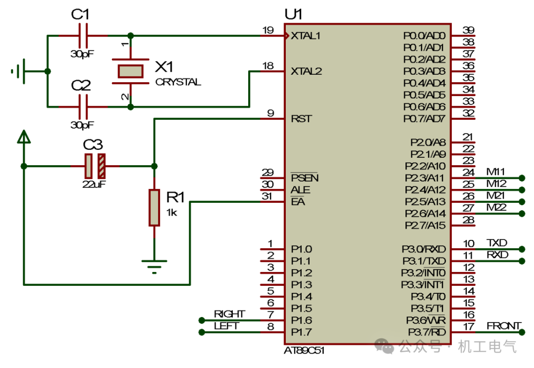
Figure 1-1 Minimum System of Microcontroller
Power Circuit of the Main Remote-Controlled Car
The power supply of the main remote-controlled car requires two lithium batteries in series, with a voltage of about +7.4V. The power circuit of the remote-controlled car mainly consists of three voltage regulator circuits for different power networks: The first voltage regulator circuit is composed of components like 7805, converting +7.4V to +5V to power the microcontroller and LED indicator light circuits; the second voltage regulator circuit is composed of components like 7805, converting +7.4V to +5V to power motor M1; the third voltage regulator circuit is composed of components like 7805, converting +7.4V to +5V to power motor M2. The power circuit of the remote-controlled car drawn in Proteus software is shown in Figure 1-2.
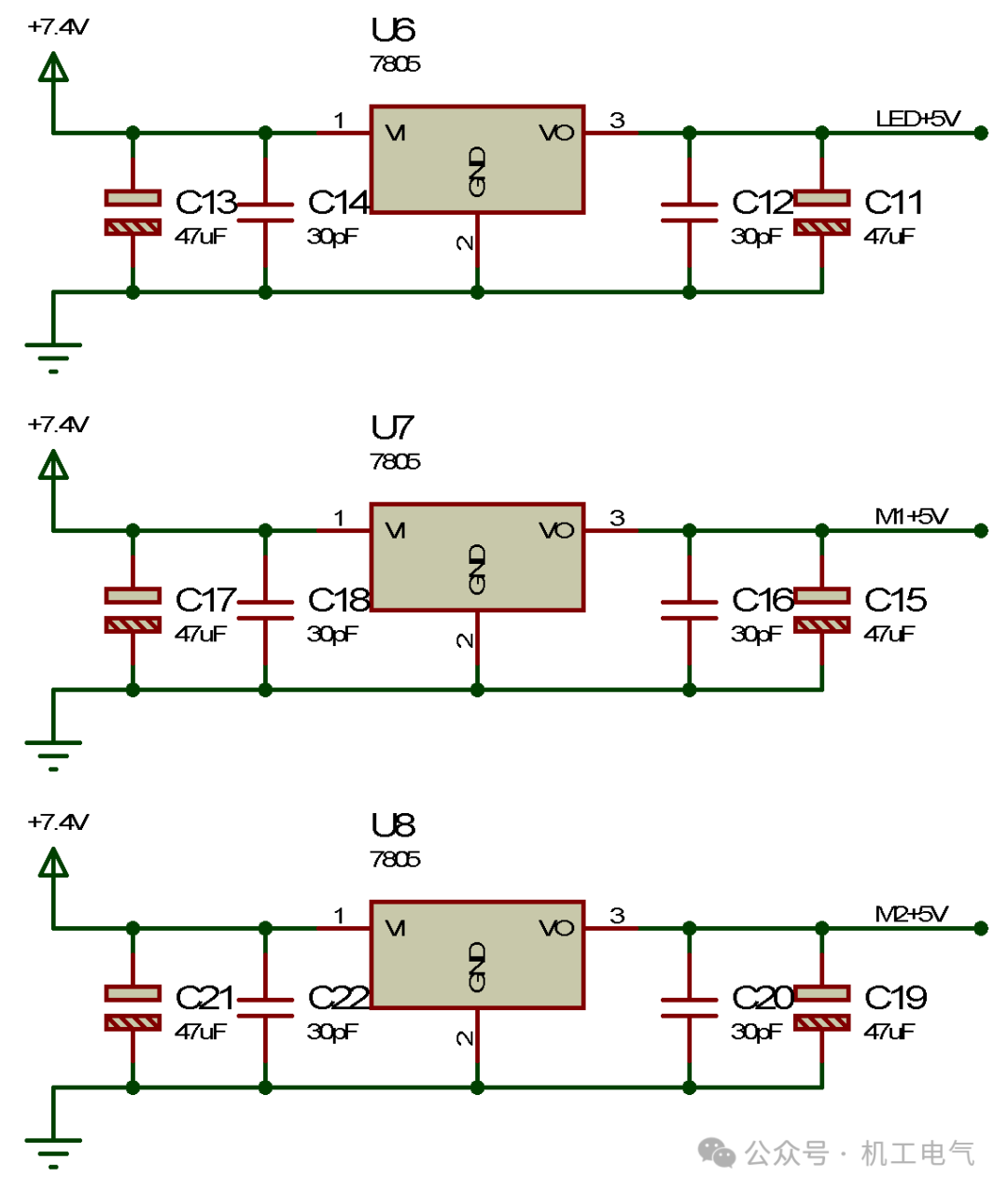
Figure 1-2 Power Circuit
Motor Drive Circuit of the Main Remote-Controlled Car
The main remote-controlled car has two drive motors and one universal wheel, thus requiring two motor drive circuits. The motor drive circuits in this example are all composed of discrete components and can drive two motors. The motor drive circuit drawn in Proteus software is shown in Figure 1-3, and it mainly consists of transistors PN4141, PN4143, diodes PN4001, resistors, and DC motors.
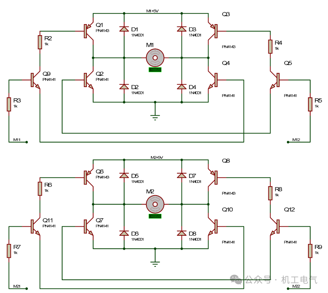
Figure 1-3 Motor Drive Circuit
The motor M1 drive circuit is connected to the P2.3 pin of the AT89C51 microcontroller through network label “M11,” connected to the P2.4 pin of the AT89C51 microcontroller through network label “M12,” and connected to the +5V power network through network label “M1+5V.” The motor M2 drive circuit is connected to the P2.5 pin of the AT89C51 microcontroller through network label “M21,” connected to the P2.6 pin of the AT89C51 microcontroller through network label “M22,” and connected to the +5V power network through network label “M2+5V.”
Indicator Light Circuit of the Main Remote-Controlled Car
The indicator light circuit of the main remote-controlled car includes an optocoupler module circuit and an LED circuit. The LED circuit drawn in Proteus software is shown in Figure 1-4, and the optocoupler module circuit drawn is shown in Figure 1-5. The pin 1 of optocoupler module U3 is connected to the P3.7 pin of the AT89C51 microcontroller through network label “FRONT,” pin 2 is connected to the ground network, pin 4 is connected to the +5V power network through network label “LED+5V,” and pin 3 is connected to the forward indicator light circuit; the pin 1 of optocoupler module U4 is connected to the P1.6 pin of the AT89C51 microcontroller through network label “RIGHT,” pin 2 is connected to the ground network, pin 4 is connected to the +5V power network through network label “LED+5V,” and pin 3 is connected to the right turn indicator light circuit; the pin 1 of optocoupler module U5 is connected to the P1.7 pin of the AT89C51 microcontroller through network label “LEFT,” pin 2 is connected to the ground network, pin 4 is connected to the +5V power network through network label “LED+5V,” and pin 3 is connected to the left turn indicator light circuit.
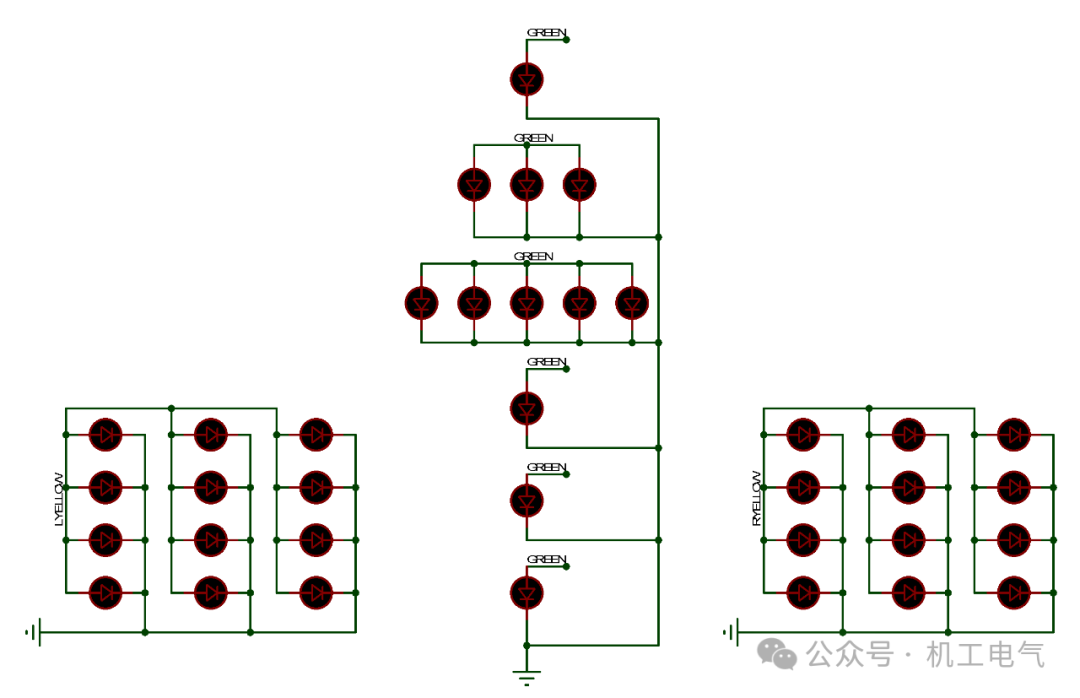
Figure 1-4 LED Circuit
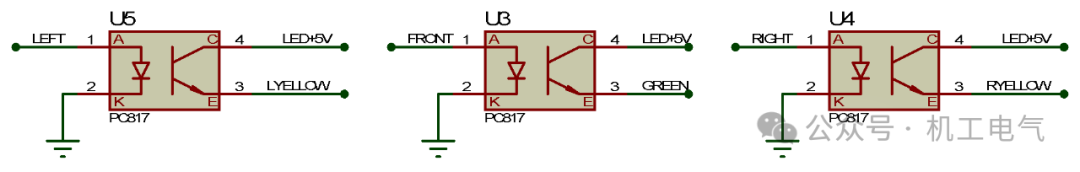
Figure 1-5 Optocoupler Module Circuit
Minimum System Circuit of the Remote Control Microcontroller
The minimum system circuit of the remote control microcontroller is shown in Figure 1-6. The P3.0 pin of microcontroller U2 is connected to the P3.1 pin of microcontroller U1 through network label “RXD,” and the P3.1 pin of microcontroller U2 is connected to the P3.0 pin of microcontroller U1 through network label “TXD.” The data collected by microcontroller U2 is transmitted to microcontroller U1 via serial communication.
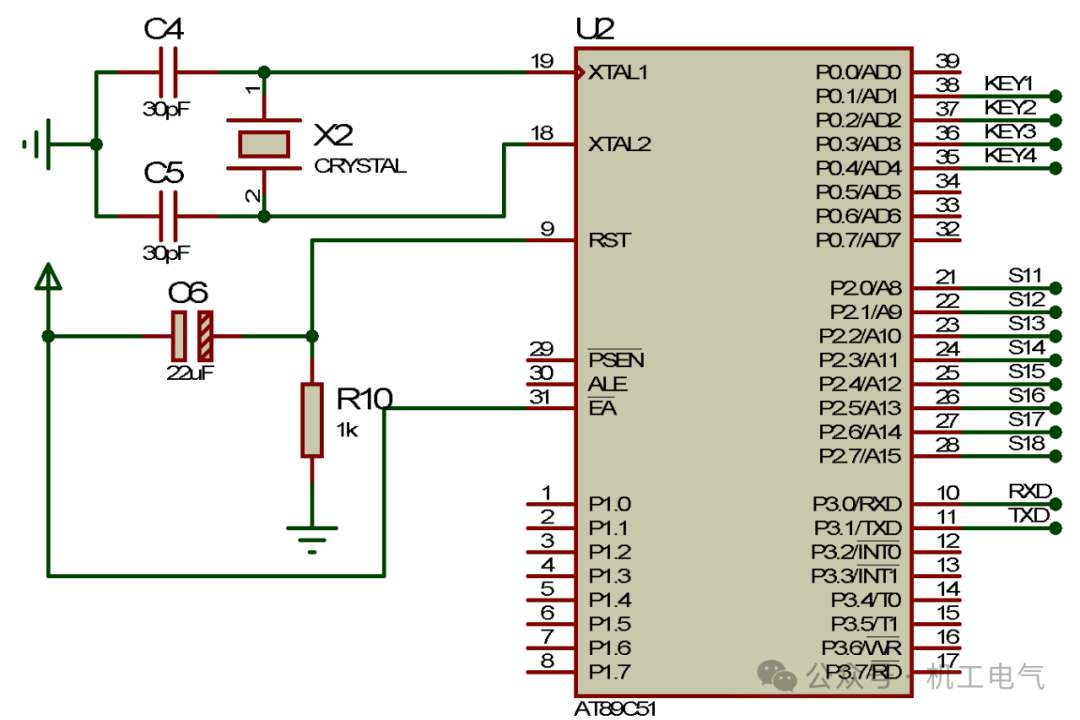
Figure 1-6 Minimum System Circuit of Remote Control Microcontroller
Indicator Module Circuit of the Remote Control
The indicator module circuit of the remote control is shown in Figure 1-7, mainly consisting of a digital tube, transistors, and resistors. Transistor Q13 is connected to the digital tube through network label “S1,” resistor R16 is connected to the P2.0 pin of microcontroller U2 through network label “S11,” and resistor R15 is connected to the +5V power network through network label “YK+5V”; transistor Q14 is connected to the digital tube through network label “S2,” resistor R18 is connected to the P2.1 pin of microcontroller U2 through network label “S12,” and resistor R17 is connected to the +5V power network through network label “YK+5V”; transistor Q15 is connected to the digital tube through network label “S3,” resistor R20 is connected to the P2.2 pin of microcontroller U2 through network label “S13,” and resistor R19 is connected to the +5V power network through network label “YK+5V”; transistor Q16 is connected to the digital tube through network label “S4,” resistor R22 is connected to the P2.3 pin of microcontroller U2 through network label “S14,” and resistor R21 is connected to the +5V power network through network label “YK+5V”; transistor Q17 is connected to the digital tube through network label “S5,” resistor R24 is connected to the P2.4 pin of microcontroller U2 through network label “S15,” and resistor R23 is connected to the +5V power network through network label “YK+5V”; transistor Q18 is connected to the digital tube through network label “S6,” resistor R26 is connected to the P2.5 pin of microcontroller U2 through network label “S16,” and resistor R25 is connected to the +5V power network through network label “YK+5V”; transistor Q19 is connected to the digital tube through network label “S7,” resistor R28 is connected to the P2.6 pin of microcontroller U2 through network label “S17,” and resistor R27 is connected to the +5V power network through network label “YK+5V”; transistor Q20 is connected to the digital tube through network label “S8,” resistor R30 is connected to the P2.7 pin of microcontroller U2 through network label “S18,” and resistor R29 is connected to the +5V power network through network label “YK+5V.”

Figure 1-7 Indicator Module Circuit
Power Circuit of the Remote Control
The remote control circuit includes the minimum system circuit of the microcontroller, independent key circuit, power circuit, and indicator circuit. The power circuit of the remote control drawn in Proteus software is shown in Figure 1-8, consisting of only one power circuit made of 7805 components, which powers the entire remote control circuit.
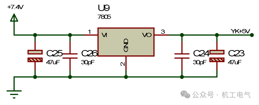
Figure 1-8 Power Circuit of Remote Control
Main Program of the Remote-Controlled Car
Start the Keil software, create a new project for the AT89C51 microcontroller, choose an appropriate save path, and name it “Car.” After creating the project, write the control program for microcontroller U1 in the main window. Define the pins of microcontroller U1, defining pin P2.3 as M11, pin P2.4 as M12, pin P2.5 as M21, pin P2.6 as M22, pin P3.7 as FRONT, pin P1.6 as RIGHT, and pin P1.7 as LEFT, as shown in the following program.
sbit LEFT = P1^7;
The remote-controlled car needs to communicate, so add the serial communication program. Only after initializing the serial communication program can microcontroller U1 receive signals sent by microcontroller U2, as shown in the following program.
}
The main function of the remote-controlled car program is to execute corresponding actions based on the signals sent by the remote control, as shown in the following program.
}
The overall program of the remote-controlled car is shown in the following program.
}
The overall program of the remote-controlled car is shown in the following program.
}
 command, after successful compilation, the HEX file will be output, as shown in the “Build Output” section in Figure 2-1.
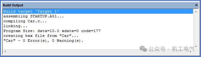
Figure 2-1 “Build Output” Section
Remote Control Program
Start the Keil software, create a new project for the AT89C51 microcontroller, choose an appropriate save path, and name it “Remote.” After creating the project, write the control program for microcontroller U2 in the main window. Define the pins of microcontroller U2, defining the P2 series pins as GPIO_DIG, defining P0.1 as Key1, P0.2 as Key2, P0.3 as Key3, and P0.4 as Key4, as shown in the following program.
sbit Key4 = P0^4;
The remote control program should also include a serial communication program so that microcontroller U2 can send signals to microcontroller U1, as shown in the following program.
}
Execute

 command, after successful compilation, the HEX file will be output, as shown in the “Build Output” section in Figure 2-2.
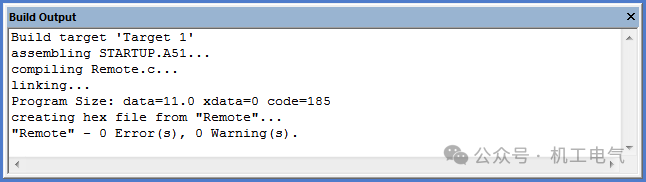
Figure 2-2 “Build Output” Section
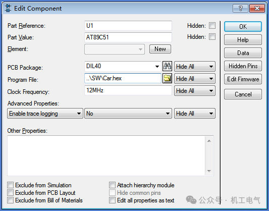
Figure 3-1 Loading HEX File into U1
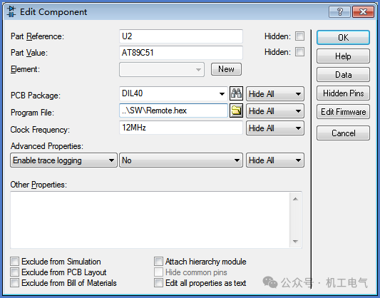
Figure 3-2 Loading HEX File into U2
 command, run the remote-controlled car circuit simulation. When entering the initial state, microcontroller U2 sends mode 0 signal to microcontroller U1. At this time, the display module of the remote control shows “0,” as shown in Figure 3-3. All the LEDs in the display circuit of the remote-controlled car are off, as shown in Figure 3-4. The DC motors in the motor drive circuit of the remote-controlled car do not rotate, as shown in Figure 3-5, indicating that the remote-controlled car is in the initial state after receiving mode 0 signal.
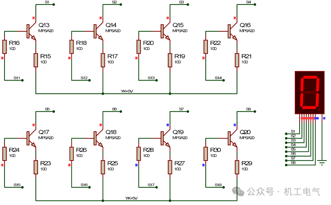
Figure 3-3 Simulation Result of the Display Module of the Remote Control 1
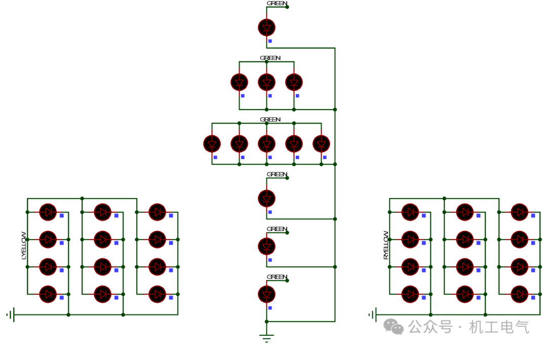
Figure 3-4 Simulation Result of the Display Circuit of the Remote-Controlled Car 1
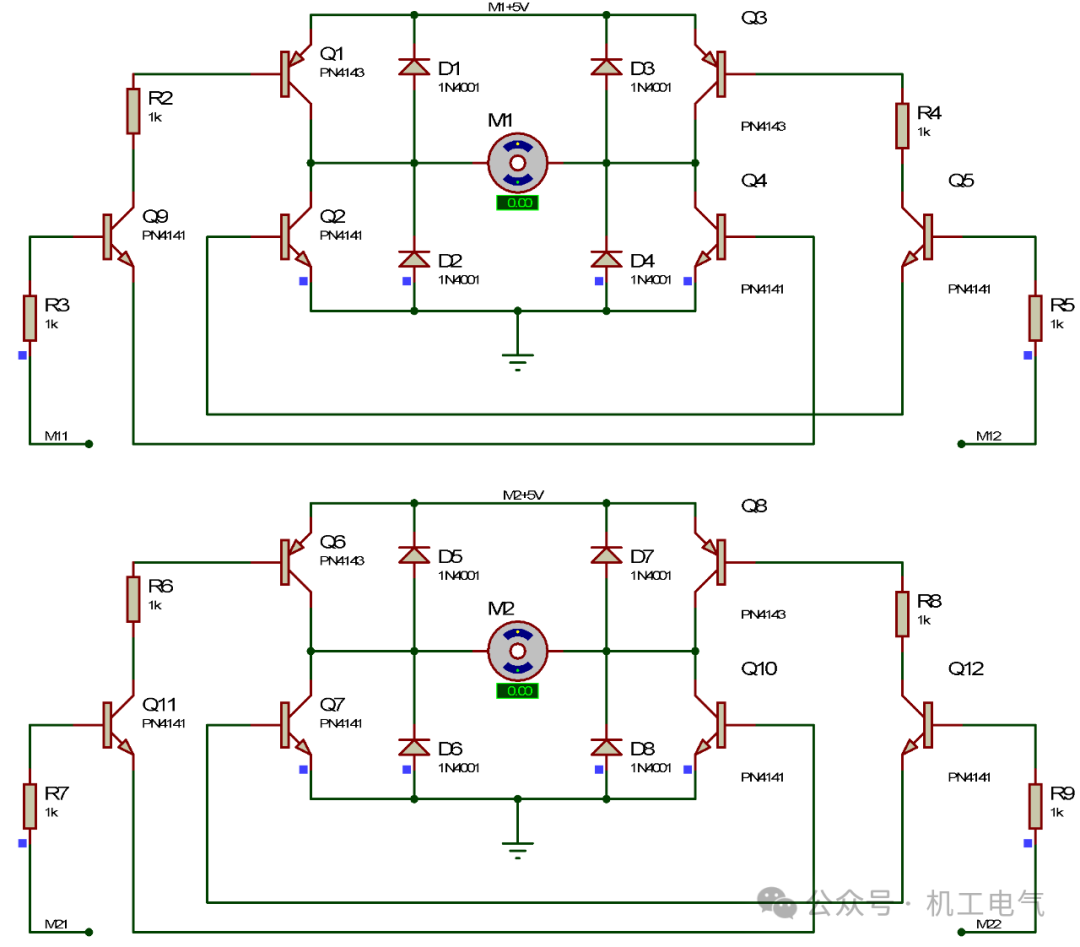
Figure 3-5 Simulation Result of the DC Motor Drive Circuit of the Remote-Controlled Car 1
Click the independent key KEY1 in the remote control circuit to send mode 1 signal to the main remote-controlled car. At this time, the display module of the remote control shows “1,” as shown in Figure 3-6. The green LED in the display circuit of the remote-controlled car lights up, and both yellow indicator lights are off, as shown in Figure 3-7. The DC motors in the motor drive circuit of the remote-controlled car rotate, as shown in Figure 3-8, indicating that the remote-controlled car starts to move forward after receiving mode 1 signal.
Click the independent key KEY2 in the remote control circuit to send mode 2 signal to the main remote-controlled car. At this time, the display module of the remote control shows “2,” as shown in Figure 3-9. The green LED in the display circuit of the remote-controlled car turns off, and the right yellow indicator light turns on while the left yellow indicator light turns off, as shown in Figure 3-10. The DC motor M1 in the motor drive circuit of the remote-controlled car rotates, and the DC motor M2 does not rotate, as shown in Figure 3-11, indicating that the remote-controlled car starts to turn right after receiving mode 2 signal.
Click the independent key KEY3 in the remote control circuit to send mode 3 signal to the main remote-controlled car. At this time, the display module of the remote control shows “3,” as shown in Figure 3-12. The green LED in the display circuit of the remote-controlled car turns off, and the left yellow indicator light turns on while the right yellow indicator light turns off, as shown in Figure 3-13. The DC motor M2 in the motor drive circuit of the remote-controlled car rotates, and the DC motor M1 does not rotate, as shown in Figure 3-14, indicating that the remote-controlled car starts to turn left after receiving mode 3 signal.

Figure 3-6 Simulation Result of the Display Module of the Remote Control 2
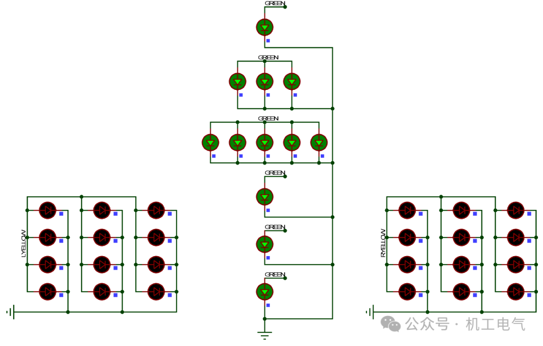
Figure 3-7 Simulation Result of the Display Circuit of the Remote-Controlled Car 2
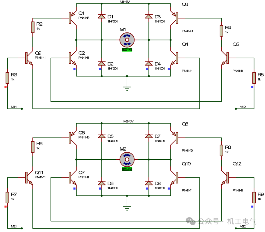
Figure 3-8 Simulation Result of the DC Motor Drive Circuit of the Remote-Controlled Car 2
Click the independent key KEY4 in the remote control circuit to send mode 4 signal to the main remote-controlled car. At this time, the display module of the remote control shows “4,” as shown in Figure 3-15. The green LED in the display circuit of the remote-controlled car turns off, the left yellow indicator lights turn on, and the right yellow indicator lights turn off, as shown in Figure 3-16. The DC motor M2 in the motor drive circuit of the remote-controlled car does not rotate, and the DC motor M1 does not rotate, as shown in Figure 3-17, indicating that the remote-controlled car stops running after receiving mode 4 signal.
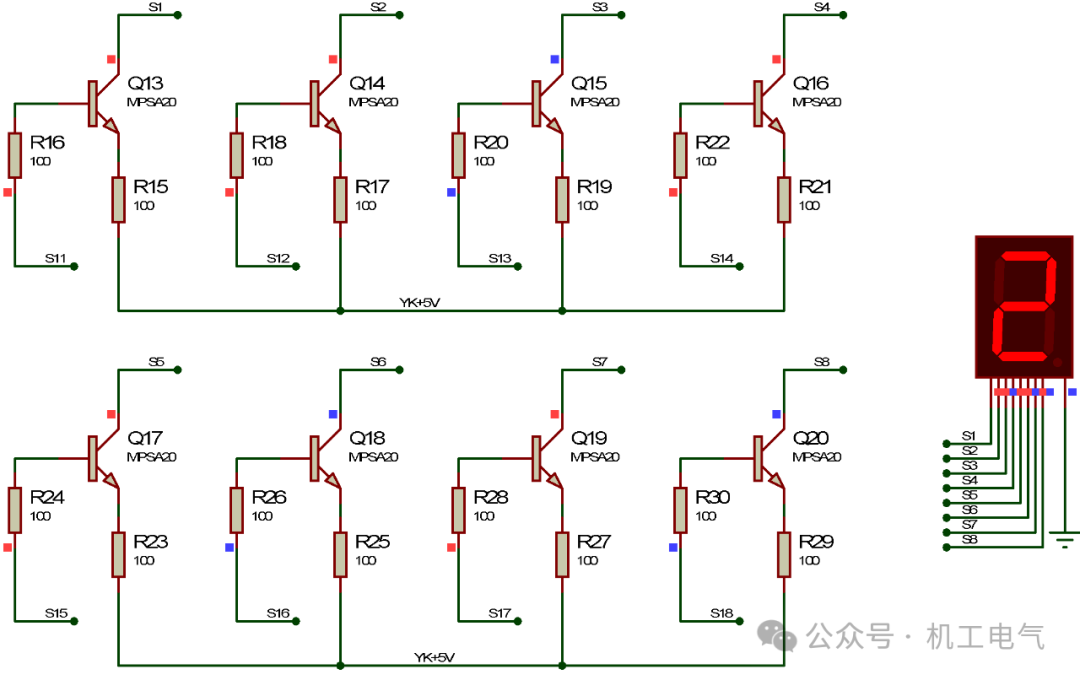
Figure 3-9 Simulation Result of the Display Module of the Remote Control 3
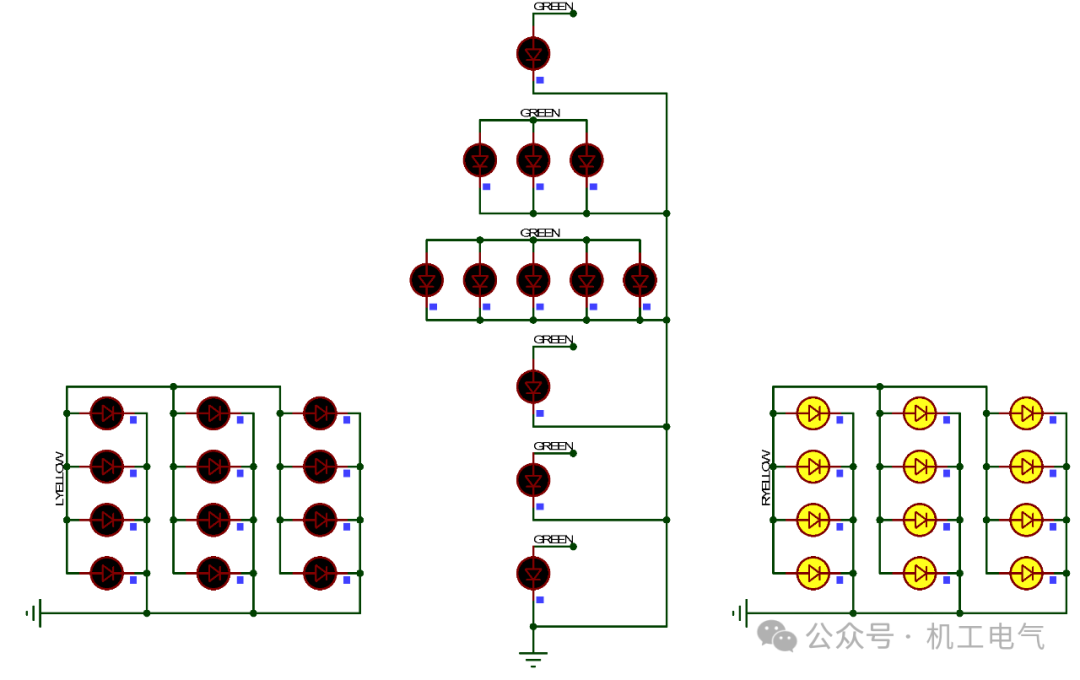
Figure 3-10 Simulation Result of the Display Circuit of the Remote-Controlled Car 3
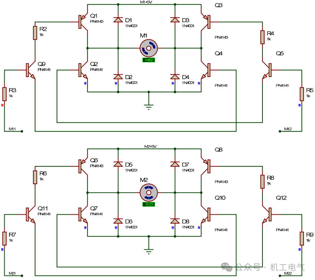
Figure 3-11 Simulation Result of the DC Motor Drive Circuit of the Remote-Controlled Car 3
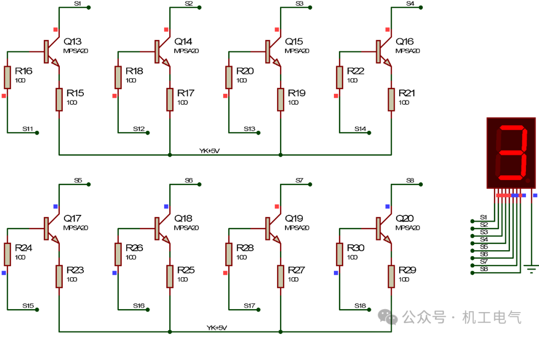
Figure 3-12 Simulation Result of the Display Module of the Remote Control 4
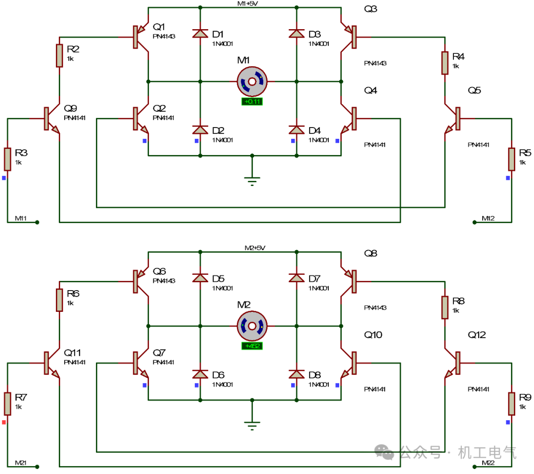
Figure 3-13 Simulation Result of the Display Circuit of the Remote-Controlled Car 4

Figure 3-14 Simulation Result of the DC Motor Drive Circuit of the Remote-Controlled Car 4

The remote-controlled car circuit consists of the main microcontroller minimum system circuit, indicator light circuit, motor drive circuit, power circuit, remote control mode display circuit, independent key circuit, and minimum system circuit of the remote control, which basically meets the requirements. This example sets up four modes, which are relatively simple. Readers can use this example as a basis to appropriately increase the types of modes and microcontroller peripherals. The independent key circuit contains four independent keys, and readers can modify the program of the remote control circuit microcontroller to reduce the number of independent keys. In practical applications, an infrared receiver can be added to the remote-controlled car circuit, along with an infrared remote control, to achieve the basic functions of the remote-controlled car.


★ All About | Step-by-Step Guide on How to DIY Biped Robot? Proteus Microcontroller Circuit Design and Simulation – A Must-Read for Electronic Design Competition Participants!
★ What design principles should engineers follow for low-voltage electrical appliances? Are there any differences between relays and contactors? Some introductory guidance for low-voltage electrical engineers – Here are some insights and suggestions from Teacher Zhang Baifan.
★ Operational Amplifier Circuit Analysis Methods and 4 Classic Basic Circuits
★ The Underlying Logic of Virtual Power Plants