Follow+Star Public Account Number, don’t miss out on exciting content
Source | Arduino Chinese Community
The Arduino UNO R4 is a new generation classic development board launched in 2023, equipped with a 32-bit Renesas RA4M1 Cortex-M4 processor, significantly improving performance and adding practical features such as Wi-Fi and DAC. It comes with 32 kB of RAM, a clock speed of 48 MHz, and a USB-C® interface.
This is the first UNO development board to use a 32-bit architecture, whereas previous versions were based on an 8-bit AVR architecture.
This article serves as a technical reference for your development board, introducing various components of the board and getting started resources.
Power Supply
You can power the UNO R4 Minima using a USB-C® cable or the VIN pin.
The development board can be powered through the VIN pin, supporting a range of 6-24 V. The VIN pin is also connected to a DC jack (barrel connector).
When powered through the VIN pin, you are using the onboard voltage regulator to step down the voltage to 5V, which means the 5 V pin can provide up to 1.2 A of current. Keep in mind that this voltage regulator also powers other components on the board, including the MCU, LEDs, etc.
External devices with high current loads (such as servo motors) should never be powered through the 5 V pin. It is primarily used for lower current devices, such as sensor modules.
If you use a USB-C® connector, you must provide a 5 V power supply.
When powered via USB, you completely bypass the onboard voltage regulator. In this case, the 5 V pin can provide up to 2 A of current without damaging the development board.
Core
The UNO R4 Minima is based on the Arduino Core for Renesas devices.
Installation
The UNO R4 Minima can be programmed using the Arduino IDE, Arduino Web Editor, or Arduino CLI.
Arduino IDE
To use this development board in the Arduino IDE, you need to install the latest version of the Arduino UNO R4 board package from the board manager.
Read more in the getting started guide for UNO R4 Minima.
Arduino Web Editor
The Web Editor is an online IDE that includes all official development boards without the need to install cores/packages. You need to install the Create plugin on your computer to use the Web Editor.
Read more in the Web Editor getting started guide.
Renesas RA4M1
The UNO R4 Minima features a powerful and robust Renesas microcontroller, also used in the UNO R4 WiFi. Renesas microcontrollers are known for their high performance and robustness, including their built-in peripheral set.
These peripherals include analog-to-digital converters, timers, pulse-width modulation (PWM) units, communication interfaces (such as UART, SPI, and I2C), etc.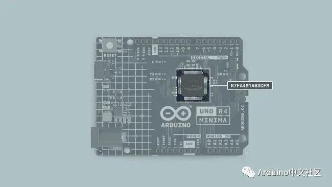
Storage Features
-
32 kB SRAM
-
256 kB flash
-
8 kB EEPROM
Pins
The UNO R4 Minima provides you with many different pins, many of which have special functions that will be explained in the following sections of this article. Continue reading to learn how you can use them.
Here is a complete table of all IO pins on the UNO R4 Minima:
| Pin | Type | Function |
|---|---|---|
| D0 | Digital | UART Receive |
| D1 | Digital | UART Transmit |
| D2 | Digital | GPIO Pin, Interrupt |
| D3 | Digital | GPIO Pin, Interrupt, PWM |
| D4 | Digital | GPIO Pin |
| D5 | Digital | GPIO Pin, PWM |
| D6 | Digital | GPIO Pin, PWM |
| D7 | Digital | GPIO Pin |
| D8 | Digital | GPIO Pin |
| D9 | Digital | GPIO Pin, PWM |
| D10 | Digital | SPI (CS), GPIO Pin, PWM |
| D11 | Digital | SPI (CIPO), GPIO Pin, PWM |
| D12 | Digital | SPI (COPI), GPIO Pin |
| D13 | Digital | SPI (SCK), GPIO Pin, Built-in LED |
| A0 | Analog | Analog Input, DAC |
| A1 | Analog | Analog Input, Op-Amp + |
| A2 | Analog | Analog Input, Op-Amp – |
| A3 | Analog | Analog Input, Op-Amp Output |
| A4 | Analog | Analog Input, SDA* |
| A5 | Analog | Analog Input, SCL* |
*A4 and A5 pins are both connected to the same I2C bus.
Analog Pins
The UNO R4 Minima has six analog input pins (A0-A5) that can be read using the analogRead() function.
| Pin | Type | Function |
|---|---|---|
| A0 | Analog | Analog Input, DAC |
| A1 | Analog | Analog Input, Op-Amp + |
| A2 | Analog | Analog Input, Op-Amp – |
| A3 | Analog | Analog Input, Op-Amp Output |
| A4 | Analog | Analog Input, SDA* |
| A5 | Analog | Analog Input, SCL* |
*A4 and A5 pins are both connected to the same I2C bus.
value = analogRead(pin);
The default reference voltage for these pins is 5 V, but it can be changed as follows:
-
analogReference(AR_DEFAULT) (default reference voltage 5 V)
-
analogReference(AR_INTERNAL) (internal reference voltage 1.5 V)
The default resolution is set to 10 bits, but it can be updated to 12 bits and 14 bits. To do this, use the following method in the setup() of your sketch.
-
analogReadResolution(10) (default)
-
analogReadResolution(12)
-
analogReadResolution(14)
To learn more about the ADC capabilities of the UNO R4 Minima, please refer to the ADC resolution guide.
Op-Amp Pins
The RA4M1 has an internal op-amp, exposed on the UNO R4 Minima as follows:
| Pin | Op-Amp |
|---|---|
| A1 | Op-Amp + |
| A2 | Op-Amp – |
| A3 | Op-Amp Output |
PWM
The PWM (Pulse Width Modulation) feature allows digital pins to simulate analog output by turning on and off very quickly, enabling you to do many things, such as dimming an LED connected to a digital pin.The UNO R4 Minima supports PWM on pins marked with ~. The officially supported pins are:
| Pin | RA4M1 | Timer |
|---|---|---|
| D3 | P104 | GTIOC1B |
| D5 | P102 | GTIOC2B |
| D6 | P106 | GTIOC0B |
| D9 | P303 | GTIOC7B |
| D10 | P112 | GTIOC3B |
| D11 | P109 | GTIOC1A |
You can use the following function as a simulated output pin:
analogWrite(pin, value);
The default resolution is 8 bits (0-255), and you can change this resolution using analogWriteResolution(), supporting up to 12 bits (0-4096) resolution.
analogWriteResolution(resolution);
Digital Pins
The UNO R4 Minima has a total of 14 digital pins. Although some of these pins have other uses, do not use them for GPIO if you have other available pins.
| Pin | Type | Function |
|---|---|---|
| D0 | Digital | UART Receive |
| D1 | Digital | UART Transmit |
| D2 | Digital | GPIO Pin, Interrupt |
| D3 | Digital | GPIO Pin, Interrupt, PWM |
| D4 | Digital | GPIO Pin |
| D5 | Digital | GPIO Pin, PWM |
| D6 | Digital | GPIO Pin, PWM |
| D7 | Digital | GPIO Pin |
| D8 | Digital | GPIO Pin |
| D9 | Digital | GPIO Pin, PWM |
| D10 | Digital | SPI (CS), GPIO Pin, PWM |
| D11 | Digital | SPI (CIPO), GPIO Pin, PWM |
| D12 | Digital | SPI (COPI), GPIO Pin |
| D13 | Digital | SPI (SCK), GPIO Pin, Built-in LED |
Additionally, the analog pins A0-A5 can also be used as digital pins. Note that A4/A5 are reserved for the I2C bus.All digital pins have a reference voltage of 5 V.
LED
The UNO R4 Minima has four LEDs, three of which are programmable:
-
ON – Power LED, not programmable.
-
LED_BUILTIN – The classic “built-in LED,” connected to pin 13.
-
RX_LED – The LED marked “RX” on the board.
-
TX_LED – The LED marked “TX” on the board.
To control these, define them as outputs and write the desired state. The example below blinks each LED once per second.
void setup() {
// Define pins as outputs
pinMode(LED_BUILTIN, OUTPUT);
pinMode(RX_LED, OUTPUT);
pinMode(TX_LED, OUTPUT);
}

void loop() {
// Turn on all LEDs
digitalWrite(LED_BUILTIN, HIGH);
digitalWrite(LED_RX, HIGH);
digitalWrite(LED_TX, HIGH);
delay(1000);

// Turn off all LEDs
digitalWrite(LED_BUILTIN, LOW);
digitalWrite(LED_RX, LOW);
digitalWrite(LED_TX, LOW);
delay(1000);
}
DAC
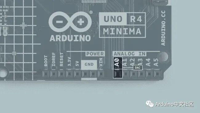 The UNO R4 Minima has a DAC with a resolution of up to 12 bits, which can serve as a true analog output pin, meaning it is more capable than PWM pins.
analogWrite(pin, value);
The default write resolution for this DAC pin is 8 bits. This means that the value written to the pin should be between 0-255. However, if needed, you can change this write resolution, up to 12 bits, in which case the value written to the pin should be between 0-4096.
analogWriteResolution(12);
To learn more about the DAC capabilities of the UNO R4 Minima, please refer to the DAC guide.
RTC
The Real-Time Clock (RTC) is used to measure time and is useful in any application that tracks time. Below is a minimal example demonstrating how to get the date and time from the RTC:
#include "RTC.h"

void setup() {
  Serial.begin(9600);

  RTC.begin();
  RTCTime mytime(30, Month::JUNE, 2023, 13, 37, 00, DayOfWeek::WEDNESDAY, SaveLight::SAVING_TIME_ACTIVE);

  RTC.setTime(mytime);
}

void loop() {
  RTCTime currenttime;

// Get current time from RTC
  RTC.getTime(currenttime);

// Print date (DD/MM/YYYY)
  Serial.print(currenttime.getDayOfMonth());
  Serial.print("/");
  Serial.print(Month2int(currenttime.getMonth()));
  Serial.print("/");
  Serial.print(currenttime.getYear());
  Serial.print(" - ");

// Print time (HH/MM/SS)
  Serial.print(currenttime.getHour());
  Serial.print(":");
  Serial.print(currenttime.getMinutes());
  Serial.print(":");
  Serial.println(currenttime.getSeconds());

delay(1000);
}
To learn more about the RTC capabilities of the UNO R4 Minima, please refer to the RTC guide.
EEPROM
EEPROM, also known as ‘data’ memory, is a type of memory that retains data even when the board is powered off. The Arduino Uno R4 Minima has 8 kB of EEPROM.
EEPROM.write(address, val);
EEPROM.read(address);
It has a limited number of write cycles, which means it is best suited for read-only applications. Ensure that you never use write() inside void loop() as you may exhaust all write cycles of the chip. Read more in the EEPROM guide.If you want to learn more about EEPROM, please refer to the article on Arduino UNO R4 Minima EEPROM.
SPI
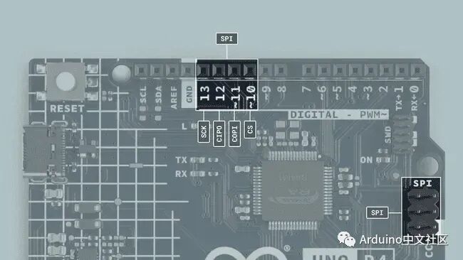 The UNO R4 Minima features a Serial Peripheral Interface (SPI) bus. The bus (connector) ‘SPI’ uses the following pins:
| Pin | Type |
|---|---|
| D13 | SCK |
| D12 | CIPO |
| D11 | COPI |
| D10 | CS |
The following example demonstrates how to use SPI:
#include <SPI.h>

const int CS = 10;

void setup() {
pinMode(CS, OUTPUT);

  SPI.begin();

digitalWrite(CS, LOW);

  SPI.transfer(0x00);

digitalWrite(CS, HIGH);
}

void loop() {
}
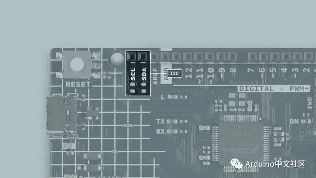
I2C
I2C Pins
I2C allows you to serially connect multiple I2C-compatible devices using only two pins. The controller will send information to a 7-bit address over the I2C bus, meaning the technical limit for I2C devices on a single line is 128. In practice, you will never reach 128 devices before other limitations arise.
The UNO R4 Minima has an I2C bus marked with SCL and SDA. They share A4 (SDA) and A5 (SCL), which users of previous UNO generations will be familiar with. There are no pull-up resistors installed on the PCB, but footprints for pull-up resistors are available if needed.
Not installing pull-up resistors at the factory has several advantages:
Since the pins used for I2C are directly connected to A4 and A5, they can also be used as digital input/output and analog input pins. If pull-up resistors are installed on these pins for I2C, it will limit their functionality solely to I2C, as they will default to a logic high level.By choosing to install different resistors, you can operate these pins with I2C devices at either 3.3 V or 5 V.The pins used for I2C on the UNO R4 Minima are as follows:
-
SDA – D18 or A4
-
SCL – D19 or A5 To connect to I2C devices, you need to include the Wire library at the top of your sketch.
#include <Wire.h>
Inside void setup(), you need to initialize the library and initialize the I2C port you want to use.
Wire.begin(); // SDA & SCL
To write to a device connected via I2C, we can use the following commands:
Wire.beginTransmission(1); // Start transmission to device 1
Wire.write(byte(0x00)); // Send command byte
Wire.write(val); // Send a value
Wire.endTransmission(); // Stop transmission
Learn more about the I2C protocol in our I2C protocol guide.
USB Serial & UART
The UNO R4 Minima board has two independent hardware serial ports.
-
One port is exposed via USB-C®.
-
The other is exposed via RX/TX pins.This is one of the several obvious differences from UNO R3 to UNO R4, as UNO R3 only had one hardware serial port, which connected to the USB port on the board and the RX/TX pins.
Native USB
Use the standard Serial object to send serial data to the computer.
Serial.begin(9600);
Serial.print("hello world");
To send and receive data via UART, we first need to set the baud rate inside void setup().
UART
The pins used for UART on the UNO R4 Minima are as follows:
| Pin | Function |
|---|---|
| D0 | RX (Receive) |
| D1 | TX (Transmit) |
| To send and receive data via UART, we first need to set the baud rate inside void setup(). Note that when using UART (RX/TX pins), we use the Serial1 object. |
Serial1.begin(9600);
To read incoming data, we can use a while loop() to read each character and add it to a string.
while (Serial1.available()) {
delay(2);
char c = Serial1.read();
  incoming += c;
}
To write content, we can use the following command:
Serial1.write("Hello world!");
Serial Event
The serialEvent() method was supported on older versions of the UNO board but is not supported on the UNO R4 board (or any other newer Arduino boards).However, since this method is only used to detect serial data and execute functions, you can also use Serial.available() to detect when new data is available:
if (Serial.available() > 0) {
// Code goes here
}
SerialUSB
The UNO R4 Minima has a set of extended Serial methods:
-
Serial.baud() – Returns the current baud rate used (int).
-
Serial.stopbits() – Returns the number of stop bits used in communication (int).
-
Serial.paritytype() – Returns the parity type used in communication (int).
-
Serial.numbits() – Returns the number of data bits used in communication (int).
-
Serial.dtr() – Returns the status of the Data Terminal Ready (DTR) signal (bool), and if the DTR signal is actively used, it will also set the ignore_dtr flag to true.
-
Serial.rts() – Returns the status of the Request to Send (RTS) signal (bool). Supported links:
-
SerialUSB.h (Github).
USB HID
This board can act as a HID (keyboard/mouse) and send keystrokes or coordinates to the computer via native USB.
keyboard.press('W');
mouse.move(x, y);
This support is enabled through the keyboard and mouse libraries that you can install from the library manager in the IDE.To learn more about the HID capabilities of the UNO R4 Minima, please refer to the HID guide.
SWD Connector
The SWD connector on the UNO R4 Minima provides a debugging option, offering advanced debugging features for more advanced users.
CAN Module
The RA4M1 in the UNO R4 Minima has a built-in CAN module compliant with the CAN 2.0A/CAN 2.0B standards.The CANRX and CANTX pins can be connected to CAN transceivers such as the MCP2551 or TJA1050 IC.
| Pin | Function |
|---|---|
| D4 | CANTX |
| D5 | CANRX |
| The built-in Arduino_CAN library is used to communicate with other CAN devices. |
// Set CAN bit rate and initialize the library from BR_125k, BR_250k, BR_500k, BR_1000k
CAN.begin(CanBitRate::BR_250k);
Construct a CAN message and send it:
uint8_t const msg_data[] = {0xCA, 0xFE, 0, 0, 0, 0, 0, 0};
memcpy((void*)(msg_data + 4), &msg_cnt, sizeof(msg_cnt));
CanMsg msg(CAN_ID, sizeof(msg_data), msg_data);
CAN.write(msg);
Read incoming CAN messages.
CanMsg const msg = CAN.read(); // Read
Note that without a CAN transceiver, you cannot communicate with other CAN devices.
Wi-Fi IoT Practical Application
#include "WiFiS3.h"
const char* ssid = "your_SSID"; const char* pass = "your_PASSWORD";
void setup() {  Serial.begin(9600);  WiFi.begin(ssid, pass);
  while (WiFi.status() != WL_CONNECTED) {    delay(500);    Serial.print(".");  }
  Serial.println("\nConnected! IP: ");  Serial.println(WiFi.localIP());}
void loop() {  if (WiFi.status() == WL_CONNECTED) {    // Add your network logic  }}
Bootloader
If you need to refresh the bootloader on the UNO R4 Minima, you can follow these steps: Step 1: Install the UNO R4 board package as described in the getting started guide. Step 2: Navigate to: “C:\Users\YourWindowsUserName\AppData\Local\Arduino15\packages\arduino\hardware\renesas_uno\1.X\bootloaders\UNO_R4” Step 3: Identify dfu_minima.hex Step 4: Install the Renesas Flash Programmer (download page)The Renesas Flash Programmer is currently only available on Windows. Step 5: Use the Renesas Programmer to refresh the bootloader:
-
Select dfu_minima.hex.
-
Connect your board.
-
Short the BOOT and GND pins on the UNO R4 Minima.
-
Go to the Connect Settings tab.
-
Select the COM port in tools > select the port shown in the IDE.
-
Press start.
———— END ————

What is the MCU standby power consumption at 0.25uA?

Playing with MCU in VS Code

Dual-core processor BOOT startup process