Hello everyone, today I will guide you through a real project—creating a smart home control system using PLC and Arduino. Why combine these two devices? The PLC is like an experienced factory master, stable and reliable but not very flexible; the Arduino is like a creative geek, rich in functionality but needs protection. By teaming them up, we can ensure system stability while achieving various smart functions!
unsetunset1. Communication Method Selection: “Encrypted Communication” Between Devicesunsetunset
1.1 Why Choose RS485 Communication
Just like two friends need to agree on a language to chat, devices also need to select a protocol for communication. Here, we recommend the RS485 bus for three reasons:
- Strong Anti-Interference: It can transmit over longer distances than common serial communication (up to 1200 meters)
- Easy Networking: A single bus can connect up to 32 devices
- Bidirectional Transmission: Supports master-slave query communication
1.2 Key Points for Hardware Modification
- PLC Side: Most PLCs come with an RS485 interface (usually labeled as Port2)
- Arduino Side: Requires a MAX485 conversion module
- Important! Remember to connect:
- Line A to Line A, Line B to Line B
- Common ground (connect GND)
- Terminal resistors at both ends of the bus
Hard-Learned Lesson: Last year during debugging, I forgot to connect the terminal resistors, resulting in intermittent communication issues that took two full days to troubleshoot!
unsetunset2. Hardware Setup: Building the Smart Home Control Hubunsetunset
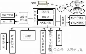
2.1 System Architecture Diagram
Mobile APP --WiFi--> Arduino --RS485--> PLC --Relay--> Lights/Curtains/Air Conditioning
              |                 |
      Temperature and Humidity Sensor      Motor Driver Module
2.2 Component List
| Device | Function Description | Reference Model |
|---|---|---|
| PLC | Core Control Execution | Siemens S7-200 SMART |
| Arduino | Data Processing and Communication Relay | Mega2560 |
| Temperature and Humidity Module | Environmental Monitoring | DHT22 |
| Relay Group | Control of High-Power Devices | 16-Channel Relay Board |
2.3 Three Key Elements of Safety Protection
- Isolation of Strong and Weak Currents: Install an optocoupler isolation module between the PLC and the relay
- Lightning Protection: Install a TVS diode at the RS485 bus entry
- Emergency Switch: Keep a physical switch control channel
unsetunset3. Software Programming: Making Devices “Understand Human Language”unsetunset
3.1 Key Arduino Code (with Comments)
#include <ModbusMaster.h>
ModbusMaster node;

void setup() {
  Serial.begin(9600);
  node.begin(1, Serial); // Set slave address to 1
}

void loop() {
  // Read data from PLC register 40001
  uint8_t result = node.readHoldingRegisters(0, 1);
  if (result == node.ku8MBSuccess) {
    int plcData = node.getResponseBuffer(0);
    // Process data...
  }

  // Send temperature data to PLC
  float temp = dht.readTemperature();
  node.setTransmitBuffer(0, (uint16_t)(temp*10)); // Scale by 10 for transmission
  node.writeMultipleRegisters(0, 1);
}
3.2 Key Points for PLC Ladder Diagram Programming
3.3 Debugging Tips
- Segmented Testing Method: First, establish communication between Arduino and PC, then connect to PLC
- Data Monitoring: Use Modbus Poll software to monitor data flow
- Error Code Table: Print common error codes to the serial monitor
unsetunset4. Typical Application Scenariosunsetunset
4.1 Smart Lighting System
- Linkage Logic: Light sensor + human infrared sensing → automatic brightness adjustment
- PLC Advantages: Precise control of the dimming module’s PWM output
- Arduino Tasks: Receive commands from the mobile APP via WiFi
4.2 Electric Curtain Control
- Safety Design:
- Stop on Obstruction (current detection)
- Timed Position Memory
- Emergency Manual Operation
4.3 Energy Management System
- Data Flow: Power meter → Arduino → Cloud → PLC executes energy-saving strategies
- Reporting Function: Generate monthly electricity analysis charts
unsetunset5. Common Problem Troubleshooting Guideunsetunset
5.1 Three-Step Method for Troubleshooting Communication Failures
- Check Power: Measure bus voltage with a multimeter (normal value 2-6V)
- Measure Waveform: Use an oscilloscope to observe differential signals on A/B lines
- Swap Devices: Cross-test to identify the fault point
5.2 Typical Fault Cases
- Data Corruption: Inconsistent baud rate settings (e.g., setting 9600 to 115200)
- Random Disconnections: Unshielded connections causing electromagnetic interference
- Address Conflicts: Multiple devices using the same station number
5.3 System Optimization Suggestions
- Data Compression: Package multiple binary signals into one register for transmission
- Heartbeat Mechanism: Periodically send detection packets to monitor online status
- Hot Standby: Add a backup controller to enhance reliability
unsetunsetPractical Suggestionsunsetunset
Basic Exercises
- Establish point-to-point communication between Arduino and PLC
- Complete remote control of LED lights
Advanced Challenges
- Add automatic temperature and humidity adjustment function
- Develop a WeChat mini-program control interface
Expansion Directions
- Integrate with HomeAssistant smart home platform
- Add UPS for uninterrupted power supply
- Develop a voice control module
Special Reminder: When operating high-power devices, always follow the safety protocol of “1. Test for voltage, 2. Isolate, 3. Operate.” There was an engineer who plugged and unplugged a relay while powered, causing the entire control board to burn out—don’t let such stories happen to you!
What automation technologies would you like to learn about next? Let me know in the comments, and maybe the next topic will be tailored for you!