In today’s rapidly advancing technology, creating a toy car that can be wirelessly controlled via a smartphone not only allows us to gain a deeper understanding of electronic circuits and programming knowledge but also brings a great sense of accomplishment. Today, let’s complete this fun project using Arduino UNO and Bluetooth Module.
1. Required Materials List
| Component | Model/Parameters | Purpose |
|---|---|---|
| Arduino UNO | Standard development board | The “brain” of the project, controlling logic |
| Bluetooth Module | HC-05/HC-06 (requires pairing and debugging) | The wireless bridge between the phone and the car |
| L298N Motor Driver Board | Dual H-bridge design, supports dual motor control | Provides power and controls direction for the motors |
| DC Motor ×2 | 12V, 200-500RPM (suitable for toy cars) | Power source for front and rear wheels |
| 12V Battery Pack | 2 AA batteries or lithium battery | Power supply system |
| Toy Car Chassis | Small car base with wheels | Integrates all hardware |
| Dupont Wires | Several | Connects circuits |
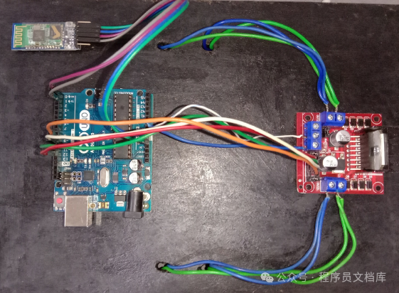
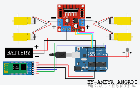
2. Hardware Connection Steps (Detailed with Images)
1. Connecting the Bluetooth Module to Arduino UNO
HC-05 Bluetooth Module → Arduino UNO:
  TXD → RX (0)        # Data reception
  RXD → TX (1)        # Data transmission
  VCC → 5V            # Power supply (do not use 3.3V!)
  GND → GND           # Common ground
HC-05 Bluetooth Module → Arduino UNO:
TXD → RX (0) # Data reception
RXD → TX (1) # Data transmission
VCC → 5V # Power supply (do not use 3.3V!)
GND → GND # Common groundKey Details:
- Use 3.3V power supply to power the Bluetooth module to avoid damaging it with excessive voltage.
- The default baud rate for HC-05 is 9600, which needs to be confirmed via AT commands (see appendix at the end).
2. Connecting the L298N Motor Driver Board to Arduino UNO
L298N → Arduino UNO:
  IN1 → D2            # Control positive direction of left motor
  IN2 → D3            # Control negative direction of left motor
  ENA → D9            # Control speed of left motor (PWM)
  IN3 → D4            # Control positive direction of right motor
  IN4 → D5            # Control negative direction of right motor
  ENB → D10           # Control speed of right motor (PWM)
  GND → GND           # Common ground
  +12V → External power positive terminal  # Motor power supply
L298N → Arduino UNO:
IN1 → D2 # Control positive direction of left motor
IN2 → D3 # Control negative direction of left motor
ENA → D9 # Control speed of left motor (PWM)
IN3 → D4 # Control positive direction of right motor
IN4 → D5 # Control negative direction of right motor
ENB → D10 # Control speed of right motor (PWM)
GND → GND # Common ground
+12V → External power positive terminal # Motor power supply3. Connecting the Motors to the Wheels
- Fix the two DC motors on either side of the chassis, with the driving wheels being the rear wheels (or adjust according to the chassis structure).
- Use zip ties or screws to secure the motor shafts to the wheels, ensuring smooth rotation.
3. Software Programming (Code Can Be Copied Directly)
// Define motor control pins
const int leftMotorPin1 = 2;
const int leftMotorPin2 = 3;
const int rightMotorPin1 = 4;
const int rightMotorPin2 = 5;
const int leftEnablePin = 9;
const int rightEnablePin = 10;

void setup() {
// Initialize pins as output mode
pinMode(leftMotorPin1, OUTPUT);
pinMode(leftMotorPin2, OUTPUT);
pinMode(rightMotorPin1, OUTPUT);
pinMode(rightMotorPin2, OUTPUT);
pinMode(leftEnablePin, OUTPUT);
pinMode(rightEnablePin, OUTPUT);

// Initialize serial communication (baud rate must match Bluetooth module)
  Serial.begin(9600);
}

void loop() {
if (Serial.available() > 0) {
    char command = Serial.read();
switch (command) {
      case 'F': // Move forward
        moveForward();
        break;
      case 'B': // Move backward
        moveBackward();
        break;
      case 'L': // Turn left
        turnLeft();
        break;
      case 'R': // Turn right
        turnRight();
        break;
      case 'S': // Stop
        stopMotors();
        break;
    }
}
}

// Function definitions
void moveForward() {
digitalWrite(leftMotorPin1, HIGH);
digitalWrite(leftMotorPin2, LOW);
digitalWrite(rightMotorPin1, HIGH);
digitalWrite(rightMotorPin2, LOW);
analogWrite(leftEnablePin, 255);
analogWrite(rightEnablePin, 255);
}

void moveBackward() {
digitalWrite(leftMotorPin1, LOW);
digitalWrite(leftMotorPin2, HIGH);
digitalWrite(rightMotorPin1, LOW);
digitalWrite(rightMotorPin2, HIGH);
analogWrite(leftEnablePin, 255);
analogWrite(rightEnablePin, 255);
}

void turnLeft() {
// Left motor backward, right motor forward → turn left
digitalWrite(leftMotorPin1, LOW);
digitalWrite(leftMotorPin2, HIGH);
analogWrite(leftEnablePin, 150);

digitalWrite(rightMotorPin1, HIGH);
digitalWrite(rightMotorPin2, LOW);
analogWrite(rightEnablePin, 255);
}

void turnRight() {
// Left motor forward, right motor backward → turn right
digitalWrite(leftMotorPin1, HIGH);
digitalWrite(leftMotorPin2, LOW);
analogWrite(leftEnablePin, 255);

digitalWrite(rightMotorPin1, LOW);
digitalWrite(rightMotorPin2, HIGH);
analogWrite(rightEnablePin, 150);
}

void stopMotors() {
digitalWrite(leftMotorPin1, LOW);
digitalWrite(leftMotorPin2, LOW);
digitalWrite(rightMotorPin1, LOW);
digitalWrite(rightMotorPin2, LOW);
analogWrite(leftEnablePin, 0);
analogWrite(rightEnablePin, 0);
}
4. Smartphone Setup
1. Bluetooth Pairing
- Set the HC-05 module to slave mode (AT+ROLE=0).
- Turn on the phone’s Bluetooth, search for devices, and connect to the device named **”HC-05″**.
2. Using Bluetooth Serial Assistant
- Download **Bluetooth Serial Assistant**
- After successful connection, send commands in the input box:
F → Move forward
B → Move backward
L → Turn left
R → Turn right
S → Stop
5. Debugging Tips and Common Issues
Q1: Unable to connect Bluetooth?
- Ensure HC-05 is in pairing mode (AT+PAIRABLE=1).
- Restart the phone’s Bluetooth or test with another phone.
Q2: The car does not move?
- Check if the power is connected (L298N’s +12V pin).
- Measure if the output voltage of the motor driver board is 12V.
Q3: Steering is not responsive?
- Adjust the servo control parameters (PWM values in the code).
- Ensure there are no obstructions on the wheel shafts.
6. Advanced Modification Suggestions
1. Add Obstacle Avoidance Function
- Use HC-SR04 Ultrasonic Sensor to detect obstacles:
int readUltrasonic() {
digitalWrite(trigPin, LOW);
delayMicroseconds(2);
digitalWrite(trigPin, HIGH);
delayMicroseconds(10);
digitalWrite(trigPin, LOW);
return pulseIn(echoPin, HIGH) * 0.034; // Convert to centimeters
}

void avoidObstacle() {
int distance = readUltrasonic();
if (distance < 20) { // When distance < 20cm, automatically brake
    stopMotors();
    delay(1000);
}
}
2. Implement Smartphone App Control
- Use Blynk or MIT App Inventor to design a custom control interface.
3. Install Camera and AI
- Use the phone camera to recognize lane lines, combined with OpenCV for automatic tracking.
Notes
- Disconnect the Bluetooth module before uploading code to avoid serial conflicts that prevent program uploads.
- The motor driver board and Arduino share GND, but the power supply must be independent (12V battery directly powered).
- Pair the HC-05 for the first time, AT command operations are detailed in the appendix at the end.
Conclusion
Through this project, you not only grasp the basic principles of embedded systems but also enhance your hands-on skills and logical thinking. Go ahead and give it a try! If you encounter any issues, feel free to ask in the comments section—your work might become the star of the next tutorial!
Appendix: HC-05 Bluetooth Module AT Command Configuration
AT+UART_DEF=9600,8,1,NONE  # Set baud rate
AT+ROLE=0                  # Set as slave device
AT+PAIRABLE=1               # Enter pairing mode
AT+NAME=MyCar              # Change device name