7.3.2 Pressure Sensors
(1) Concept
A pressure sensor is a device that converts pressure signals (primarily the pressure of gases or liquids) into quantifiable electrical signals. Its working principle involves pressure acting directly or indirectly on the sensor’s pressure-sensitive element (such as piezoresistive, capacitive, or piezoelectric elements), causing changes in the electrical parameters (such as resistance, capacitance, charge, etc.) of that element. These signals are then detected and amplified by corresponding measurement circuits, outputting a standard electrical signal (such as 4-20mA, 0-10V, etc.) that is proportional to the pressure. Pressure sensors are widely used in industrial environments, such as in the monitoring of pipeline and tank pressures in the petroleum, chemical, and pharmaceutical industries.
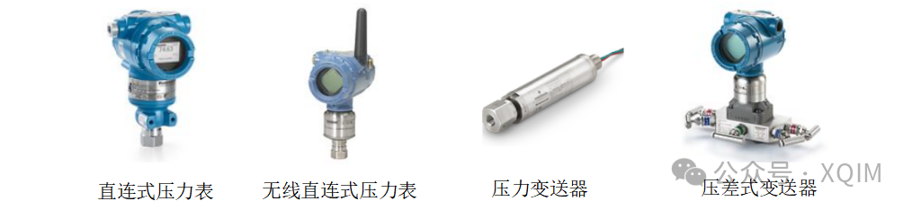
Figure 7-63 Pressure Sensor
(2) Types
There are many classification methods for pressure sensors; here are several common classification methods:
1. By working principle:
1) Piezoresistive Pressure Sensors: This is the most commonly used type of pressure sensor. It utilizes the “piezoresistive effect” of semiconductor materials. When pressure is applied to a silicon diaphragm, its resistance changes, and the change in output voltage is detected through a Wheatstone bridge, allowing for the corresponding pressure value to be determined. Piezoresistive pressure sensors are characterized by high accuracy, small size, and fast response.
2) Capacitive Pressure Sensors: One end uses a metal or ceramic diaphragm as the movable plate, while the other end is a fixed plate, forming a capacitor. Changes in pressure cause deformation of the diaphragm, altering the distance between the capacitor plates and resulting in a change in capacitance. The advantages of this type of sensor include high sensitivity, strong overload capacity, and low power consumption, making it suitable for low-pressure and micro-pressure measurements.
3) Piezoelectric Pressure Sensors: This type of sensor is designed based on the “piezoelectric effect,” where certain materials generate electric charges when subjected to pressure. These sensors are suitable for measuring dynamic pressures and cannot be used for static pressure measurements, such as cylinder pressure in engines or shock waves from explosions.
4) Ceramic Piezoresistive Pressure Sensors: These sensors use ceramic materials that are resistant to corrosion and wear, making them suitable for harsh industrial environments, especially in contact with corrosive media.
5) Sapphire Pressure Sensors: Utilizing the properties of silicon-sapphire combinations, these sensors exhibit excellent metering characteristics and high reliability, capable of operating in extreme high temperatures (>150°C) and corrosive media.
6) Sputtered Thin Film Pressure Sensors: These sensors use a sputtering process to directly coat strain gauges onto metal diaphragms, avoiding issues of creep and hysteresis associated with adhesives, and providing excellent long-term stability and resistance to shock and vibration, suitable for industrial applications requiring high reliability.
2. By measurement reference:
1) Absolute Pressure Sensors: Measure pressure relative to a perfect vacuum (zero pressure). For example, used for measuring atmospheric pressure.
2) Gauge Pressure Sensors: Measure pressure relative to local atmospheric pressure. For example, tire pressure, pipeline pressure.
3) Differential Pressure Sensors: Simultaneously measure the pressure difference between two pressure ports (high pressure and low pressure). For example, used for measuring liquid levels or pressure values in pressure vessels.
3. By measurement medium:
1) General Type: Used for non-corrosive and conventional media such as air, water, and oil.
2) Corrosion-resistant Type: The parts in contact with the medium are made of materials such as stainless steel (e.g., 316L), Hastelloy, tantalum, or ceramics, used for measuring corrosive media such as acids and bases.
(3) Main Parameters
1) Measurement Type: Different sensor types have different structural forms; the types here include absolute pressure, gauge pressure, and differential pressure. The following figure illustrates the measurement types of the Rosemount 3051 pressure sensor.
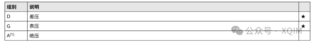
Figure 7-64 Measurement Types of Rosemount 3051 Pressure Sensor
2) Pressure Range: The range of pressure that the sensor can measure. When selecting, the normal operating pressure should be around 60%-80% of the range to avoid long-term operation at full scale and to allow for some overpressure margin, while the range should not be too large, as larger ranges can lead to lower accuracy.
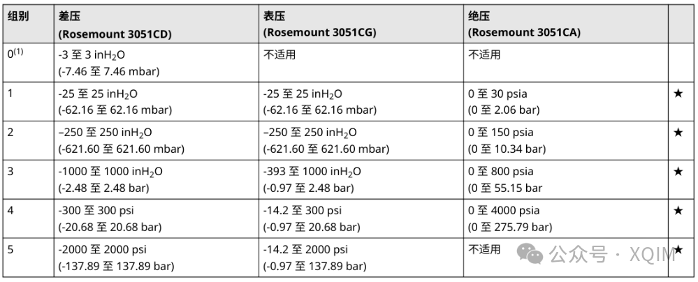
Figure 7-65 Measurement Range of Rosemount 3051 Pressure Sensor
3) Sensor Accuracy: Indicates the maximum deviation between the measured value and the true value, usually expressed as a percentage of full scale (%FS), such as ±0.5%FS.
4) Output Interface: Such as 4-20mA, 0-10V, HART communication, wireless communication, etc.
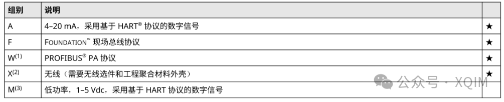
Figure 7-66 Output Interface of Rosemount 3051 Pressure Sensor
5) Diaphragm Material: This mainly considers whether the measurement medium is compatible; the materials shown in the figure, such as 316L SST and C-276 alloy, are suitable for acidic environments.
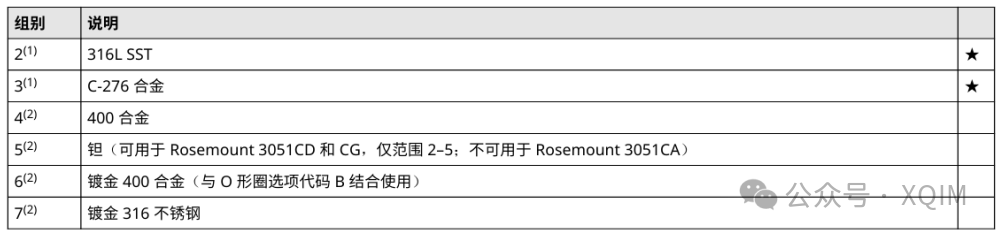
Figure 7-67 Diaphragm Material of Rosemount 3051 Pressure Sensor
6) Structural and Installation Information: This mainly includes the size of the pressure sensor’s connection to the piping and the installation dimensions of the sensor on the pipeline.
(4) Selection
Similar to temperature sensors, the selection of pressure sensors in process control systems (especially DCS control systems) generally involves filling out an “Instrument/Control Conditions Table”. After clarifying the requirements for the instrument, suppliers can be consulted for selection. A typical instrument conditions table for pressure sensors includes the following content (as shown in Figure 7-67):
1) Control Point Information of the Sensor, such as instrument tag number, purpose, and quantity;
2) Information about the Measured Medium, mainly including the name, temperature, density, etc.;
3) Control System Requirements, including installation form (field installation, centralized field, centralized control room) and control functions (Q for accumulation, I for indication, R for recording, C for control, A for alarm, S for interlock, K for remote control, etc.)
4) Specifications of the Installation Pipeline, mainly including pipeline size, material, and insulation thickness;
5) Pressure Measuring Elements, such as types of measuring elements (diaphragm pressure gauge, pressure transmitter, etc.), accuracy (e.g., class 1.6), materials of measuring elements, wetted materials, filling liquids, process connection forms and sizes;
6) Transmitter and Housing Specifications, such as housing specifications (e.g., housing diameter, whether it has a button LCD, etc.), housing material (e.g., 304), measurement range, output signal (4-20mA, HART bus, etc.), electrical interface dimensions (e.g., M20*1.5F), explosion-proof grade, protection grade, etc.;
7) Diaphragm Seal Specifications, mainly including diaphragm seal forms, diaphragm types, diaphragm materials, filling liquids, capillary lengths, process connection forms, process connection specifications, flange surfaces, flange materials, etc.
8) Accessories: Mainly including content and materials of accessories;
Note: Since the selection of instruments and valves greatly affects the control results and data accuracy of the process control system, larger enterprises typically have instrument engineers responsible for this selection. It is recommended that the selection of instruments and valves be handled by experienced engineers and confirmed by suppliers.
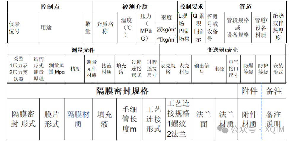
Figure 7-68 Reference Table Header for Pressure Sensor Selection
(5) Precautions
In addition to accurate selection, the installation and use of pressure sensors also require attention:
1) When installing the sensor, especially avoid damaging the threads or diaphragm. Pay particular attention to the diaphragm being installed without pressure or damage, and consider adding a protective film to prevent foreign objects from entering.
2) When measuring liquid or steam pressure, the sensor should be installed on the side wall to avoid blockage by sediment or direct impact from high-temperature steam on the diaphragm.
3) For measuring small pressures, keep the pressure tubing straight to avoid static pressure errors caused by height differences in the tubing.
4) In systems with severe pressure fluctuations or potential water hammer or gas hammer effects, install pressure buffer tubes or overpressure protection valves to protect the sensor diaphragm.
5) Ensure medium compatibility: Pressure sensors especially need to consider compatibility with the medium. For highly corrosive, high-viscosity, or easily crystallizing media, consider using isolation diaphragm sensors or special materials.
6) Follow the wiring instructions strictly; output signal wires should use shielded cables and ensure good grounding to resist electromagnetic interference.
7) High-precision pressure sensors should be powered on and preheated for a period before measurement to eliminate temperature drift effects.
8) To ensure long-term measurement accuracy, sensors should be periodically calibrated by qualified metrology institutions according to relevant standards and specific usage conditions.
————————————————————————