Hello everyone! As a seasoned player in smart manufacturing production line projects, I deal with various digital devices every day. Today, I want to share how two crucial “grassroots employees” in the digital production line—PLCs (Programmable Logic Controllers) and sensors—work together to achieve “networking” and intelligent collaboration between devices.“““
PART 01Chapter 1: Starting from the “Nervous System” of the Production Line
When visiting a digital production line, we often see robotic arms assembling precisely, conveyor belts transporting orderly, and inspection equipment sorting automatically. Behind this smooth operation is a precise network similar to the human nervous system. If we compare the entire production line to the human body, then PLCs are the “spinal cord” and “peripheral ganglia” of the production line, responsible for receiving instructions, processing information, and controlling muscle movements; while various sensors are the production line’s “sensory organs,” such as eyes (visual sensors), skin (temperature and pressure sensors), and ears (acoustic sensors), constantly collecting information from the internal and external environment. It is this close cooperation that gives the production line the intelligent cycle capability of “perception-decision-execution.” Especially in high-end manufacturing, the high demands for precision, reliability, and real-time performance make the collaboration between PLCs and sensors particularly critical.
PART 02Chapter 2: Understanding the “Ganglia” of the Digital Production Line—PLC 2.1What is a PLC?
PLC stands for Programmable Logic Controller, a digital computing electronic system specifically designed for industrial environments. It was born in the late 1960s, with core features including:
-
Industrial-grade Robustness: Able to withstand harsh industrial environments such as temperature, humidity, vibration, and electromagnetic interference;;
-
Real-time Determinism: Ensures signal processing and response are completed within a predetermined time;;
-
Programmability: Control logic can be changed through software without rewiring;;
-
Modular Design: Can be expanded with I/O modules, communication modules, etc., as needed;;
 2.2Internal Working Principle of PLCs
The working mode of a PLC is cyclic scanning, mainly divided into three stages:
1.Input Sampling Stage: The PLC reads the status of all input terminals and stores it in the input image area;
2.Program Execution Stage: The CPU executes the user program in sequence, processing input data;
3.Output Refresh Stage: Writes the computation results to the output terminals, driving external devices;
This cyclic scanning mechanism ensures predictable processing, with typical scanning cycles ranging from 1 to 100 milliseconds, and high-speed PLCs can reach microsecond levels. For some precision machining processes, this real-time capability is crucial.
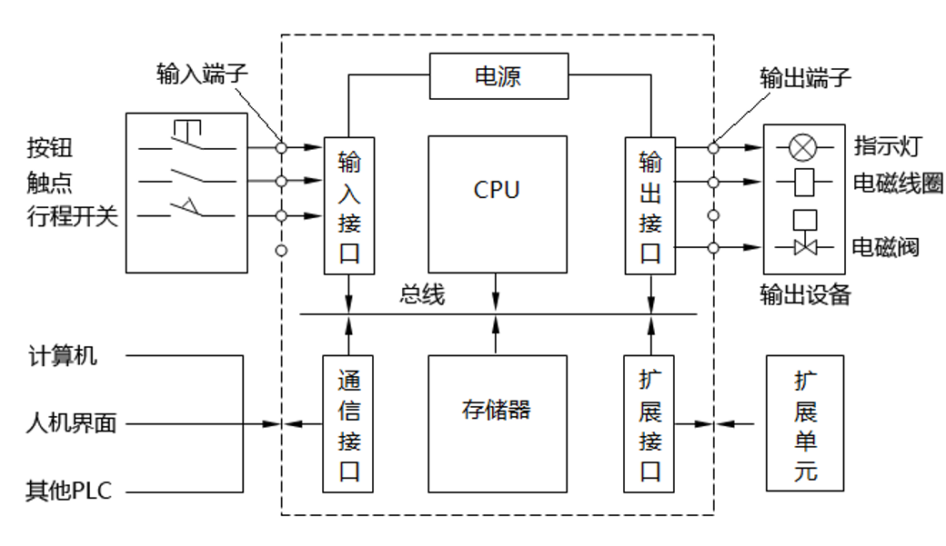 Figure 1: PLC SchematicPART 03Chapter 3: Understanding the “Sensory Organs” of the Digital Production Line—Sensors
 3.1Overview of Industrial Sensors
Sensors are devices that can sense measured information and convert it into electrical signals or other required forms according to certain rules. In the digital production line, there are various types of sensors:
-
Position Sensors: Photoelectric switches, proximity switches, encoders, etc.;
-
Visual Sensors: Industrial cameras, 3D vision systems;
-
Force/Pressure Sensors: Load cells, pressure-sensitive films;
-
Temperature Sensors: Thermocouples, thermistors, infrared thermometers;
-
Safety Sensors: Safety light curtains, area scanners;
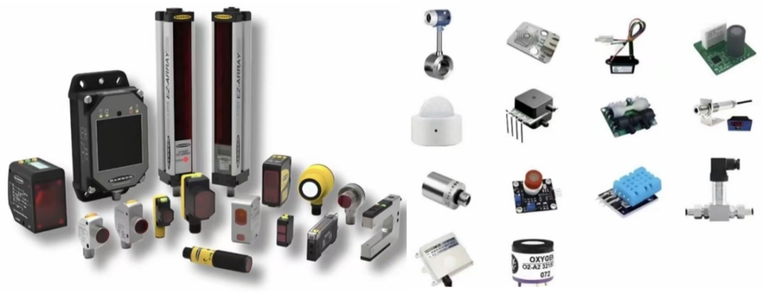 Figure 2: Sensor Diagram
 3.2Differences in Sensor Working Principles
Different types of sensors operate based on different physical principles:
-
Proximity Switches operate based on electromagnetic induction (detecting metals) or capacitance changes (detecting non-metals);
-
Photoelectric Sensors detect object occlusion by emitting and receiving light beams;
-
Encoders convert the angle or linear displacement of an axis into digital pulse signals.
In precision assembly, it may be necessary to use grating rulers with resolutions down to the micrometer level, or temperature sensors capable of detecting temperature differences of 0.1°C, ensuring products are manufactured under strict process parameters.
PART 04Chapter 4: How do PLCs and Sensors Work Together? 4.1Hardware Connection: Dialogue at the Signal Level
The connection between PLCs and sensors is mainly through the following types of signals:
-
Digital Signals: Simple switch signals (0/1), such as photoelectric sensors detecting the presence of objects;
-
Analog Signals: Continuously varying voltage/current signals (such as 0-10V, 4-20mA), such as temperature sensor measurements;
-
Dedicated Communication Buses: Such as PROFIBUS, DeviceNet, IO-Link, etc., supporting richer data exchange.
For example, in a typical workpiece detection station: a photoelectric sensor detects the workpiece’s position (digital signal) → a pressure sensor detects the clamping force (analog signal) → a visual sensor detects the workpiece’s position (communication bus) → all information is summarized to the PLC → the PLC starts the next process after determining it is qualified.
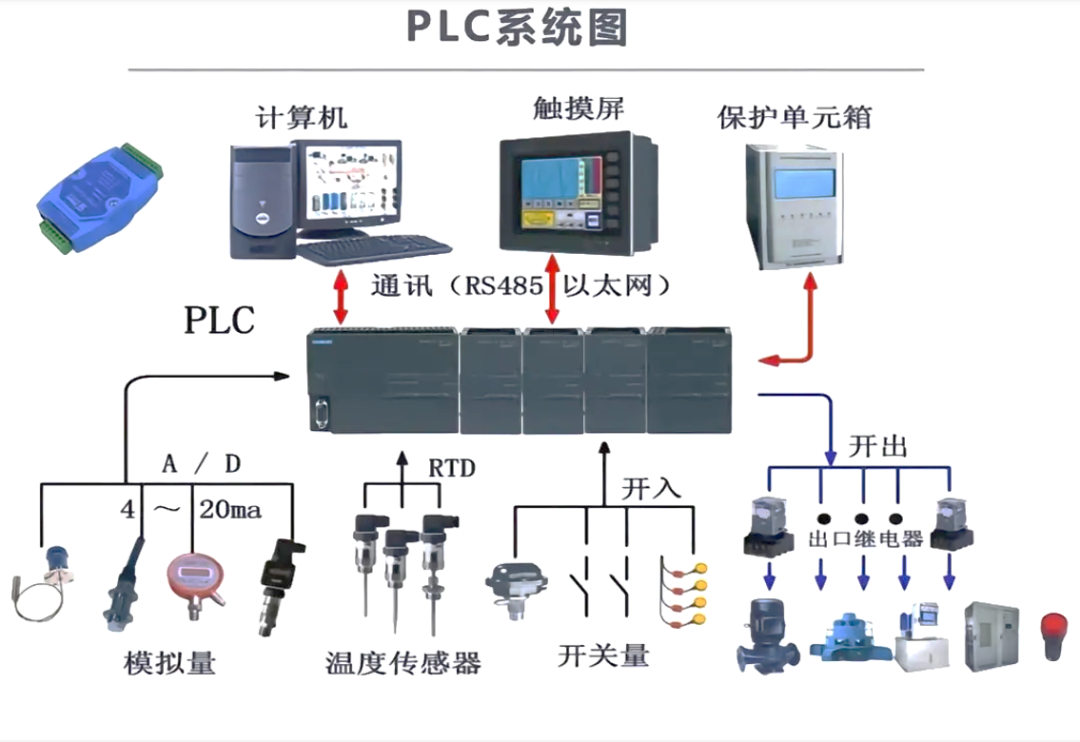 Figure 3: PLC System Diagram
 4.2Software Interaction: Logical Coordination in Programs
In the PLC program, sensor data is transformed into the basis for conditional judgments:
IF workpiece position sensor=ON AND clamping force sensor value>50N THEN
Start processing flow
ELSE
Alarm prompt
END _IF
This simple “if-then” logic chain, when combined, forms complex automation control of the production line.
 4.3Real-time Response: The Key to Closed-loop Control
In high-precision product processing, real-time adjustment of process parameters is often required. For example, in laser welding applications: sensors monitor the weld seam temperature in real-time → PLC compares the temperature with the set value → calculates the deviation → adjusts the laser power → sensors detect again to form a closed loop. This real-time closed-loop control ensures the consistency of process quality and is a core manifestation of the intelligence of the digital production line.
PART 05Chapter 5: Case Study Analysis 5.1Case Study of an Automated Testing Line for Circuit Boards
In a large-scale testing line for high-end electronic equipment circuit boards, the Programmable Logic Controller (PLC) serves as the core control unit, working in collaboration with various high-precision sensors to form the “nervous center” and “perception system” of the entire production line. The precision of this collaboration directly determines the accuracy of test results, the stability of testing efficiency, and the reliability of product quality. This production line is mainly used for the full-process automated testing of high-density, highly integrated circuit boards, eliminating subjective errors and efficiency bottlenecks caused by manual testing.
Below, we will elaborate on the collaborative mechanisms of each link:
1.Identity Recognition and Program Matching:
After the circuit board enters the testing station, the RFID (Radio Frequency Identification) sensor installed at the entrance of the conveyor track quickly reads the electronic tag information embedded on the surface of the circuit board. This information includes the model, batch, production number, and corresponding testing project list of the circuit board. The sensor transmits this identity data in the form of high-frequency signals to the main PLC, which has a massive database of preset testing programs. Within 100ms of receiving the identity information, it can complete program matching and invocation, automatically configuring the various parameter thresholds for subsequent testing links, achieving a customized testing mode of “one board, one program,” thus avoiding program miscalls during mixed-line testing of different models of circuit boards.
2.High-Precision Positioning and Alignment:
After the circuit board enters the testing area, it must achieve precise contact with the test fixture’s probes; otherwise, poor contact may lead to distorted test data or even damage to the probes and circuit board. Therefore, the system is equipped with a high-precision positioning module composed of laser displacement sensors and visual positioning sensors. The laser displacement sensor detects the height deviation of the circuit board from a vertical direction, while the visual positioning sensor identifies the positioning markers on the edges of the circuit board from a horizontal direction. The data from both sensors is fused and transmitted to the PLC.
PLC adjusts the servo motor of the conveyor platform in real-time through the motion control module, controlling the positioning accuracy of the circuit board within ±0.1mm. This level of precision fully meets the testing requirements for high-density pin chips, ensuring that each test point can maintain stable contact with the probes.
3.Multi-Dimensional Electrical Parameter Testing:
Electrical performance is the core criterion for determining whether a circuit board is qualified. The system is equipped with various dedicated electrical sensors, such as voltage sensors, current sensors, and signal acquisition sensors, to perform synchronous testing on key parts of the circuit board’s power supply circuit and signal transmission circuit. The voltage sensor uses differential measurement methods to accurately capture voltage fluctuations of ±0.01V; the current sensor employs a non-contact Hall effect principle to avoid additional load on the circuit; the signal acquisition sensor can capture high-frequency signal waveforms in real-time and convert them into digital signals for transmission to the PLC. The sampling frequency of these sensors can reach 1kHz, ensuring that no momentary parameter anomalies are missed, providing comprehensive data support for the PLC‘s analysis and judgment.
4.Monitoring Temperature Rise of Key Components:
During the powered testing of the circuit board, core chips and other power devices will generate a certain amount of temperature rise. If the temperature rise is too high, it indicates potential performance issues with the device. Even if the current electrical parameters are qualified, long-term use may lead to failures. Therefore, the system installs infrared temperature sensors at key positions of the testing fixture. These sensors use non-contact measurement methods to monitor the temperature changes on the surface of the chips in real-time without affecting the circuit board’s working state, with a sampling interval of 50ms. When a certain chip’s temperature rise rate exceeds 5°C/s or the peak temperature exceeds 70°C, the sensor immediately sends a warning signal to the PLC, providing important evidence for the PLC to assess product stability.
5.Appearance Quality Inspection:
In addition to electrical performance, the quality of solder joints and component installation on the circuit board is also an important aspect of testing. This link is completed by high-definition visual sensors. The visual sensors capture images of the solder joint areas and component layouts of the circuit board using 4K high-definition cameras, combined with specialized image recognition algorithms to automatically identify defects such as cold solder, false solder, bridging, and issues like misplacement, omission, and reverse installation of components. The sensors compare the captured image data with preset standard templates, converting the comparison results into quantitative data transmitted to the PLC, achieving automated identification of appearance defects with an accuracy rate of over 99.5%, far exceeding the efficiency and precision of manual visual inspection.
All types of data collected by the sensors are transmitted in real-time to the main PLC via the industrial Ethernet PROFINET network. The PLC integrates a dedicated data processing module, employing multi-threaded parallel processing technology, capable of completing comprehensive analysis, logical judgment of all sensor data, and generating testing reports within 500ms. For products deemed qualified, the PLC controls the pneumatic valve actions of the sorting mechanism to send them to the qualified product conveyor line; for unqualified products, they are diverted to the corresponding unqualified product storage area based on defect types (such as electrical parameter anomalies, appearance defects, temperature rise exceeding standards, etc.), and the defect reasons are marked on the system interface for subsequent rework processing.
To ensure continuous operation of the production line and avoid downtime caused by sensor failures, the system employs a dual-redundancy design: at core positions such as identity recognition, positioning, and key electrical parameter testing, two identical sets of sensors are configured. When the main sensor is operating normally, the backup sensor remains in a hot standby state, synchronizing the working parameters of the main sensor in real-time. Once the PLC detects anomalies in the main sensor’s data (such as signal interruption, excessive data fluctuations, etc.), it immediately triggers the redundancy switching mechanism, and the backup sensor takes over within 100ms, simultaneously issuing alerts through the production line’s sound and light alarm system and uploading fault information to the MES system, notifying maintenance personnel for repairs, greatly reducing production losses caused by sensor failures.
PART 06Chapter 6: Conclusion
PLCs (Programmable Logic Controllers) and sensors, this pair of “golden partners” in the digital production line, act as the “brain” and “nerve endings” of intelligent equipment. Through stable and reliable hardware interfaces and rigorous and efficient software logic programming, they perfectly achieve intelligent “networking,” data intercommunication, and precise collaborative operations among various production devices. Sensors act as sensitive “perception organs,” constantly capturing various physical signals such as temperature, pressure, position, and speed on the production line, transforming cold industrial data into recognizable electrical signals; while the PLC plays the role of the “decision-making center,” accurately receiving these signals, quickly computing and judging based on preset program logic, and issuing control commands such as start, stop, speed adjustment, and direction change to the actuators. The two work in tandem, forming a closed-loop intelligent control system.
This collaboration may seem like a basic configuration in industrial scenarios, but it is, in fact, the core framework supporting digital transformation and the key foundation for the implementation of intelligent manufacturing. In automotive welding production lines, displacement sensors monitor the motion trajectory of robotic arms in real-time, while the PLC fine-tunes servo motor parameters based on data to ensure the welding gun operates within a precision of 0.02 millimeters; in food packaging workshops, photoelectric sensors identify deviations in the position of packaging bags, and the PLC immediately corrects the conveyor belt speed to avoid issues like missed seals or incorrect seals; in photovoltaic module production, visual sensors capture tiny cracks in silicon wafers, and the PLC quickly triggers sorting mechanisms to accurately divert unqualified products—these scenarios demonstrate the ubiquitous collaboration between the two.
It is precisely these silent yet efficient “dialogues” that connect originally isolated and cold machines into an organic whole, endowing them with intelligent “life” to perceive the environment, judge states, and autonomously adjust. This has allowed traditional production lines to break free from the limitations of relying on manual monitoring, achieving continuous, precise, and intelligent production. From the automation control of individual devices to the collaborative linkage of entire production lines, and to the overall operation of smart factories, the collaboration between PLCs and sensors remains the most fundamental and core support, writing the underlying logic of intelligent manufacturing with their technical synergy.
 Tian Sheng Hua Information
Tian Sheng Hua Information has been deeply rooted in the national defense and military industry for many years, with a profound understanding of the military manufacturing model, rich accumulation of digitalization and automation business, and a firm commitment to “Made in China” by focusing on military intelligence, serving our customers.
Follow us
Learn more