Fiber Optic Sensor Technology and Advantages
Due to the extremely high purity of modern optical fibers, fiber-based sensing instruments are receiving increasing attention. The signal loss in optical fibers during long-distance transmission is minimal (<0.2 dB/km), combined with the most advanced precision optical technologies, making them highly attractive for complex sensing applications.
In addition to traditional optical surface strain detection methods (such as Moire fringe analysis or non-contact laser speckle interferometry), fiber-based strain measurement methods (such as fiber Fabry-Perot sensors, tapered fibers, and Bragg fibers) are functionally similar to electrical methods but have significant advantages in several metrological characteristics and performance:
-
Electromagnetic Interference Immunity: Completely unaffected by electromagnetic interference, and no power supply is required at the measurement site, making it applicable even in high-voltage areas or explosive environments.
-
Corrosion Resistance and Moisture Resistance: Good corrosion and moisture resistance, suitable for use in humid and harsh environments.
-
Excellent Measurement Performance: Especially for fiber Bragg sensors (FBS), which exhibit good long-term signal stability, the fastest response speed, and are suitable for high strain detection (≥10,000 μm/m).
-
Multipoint Measurement and Reusability: Multiple sensors can be integrated simultaneously in a single fiber, allowing for the measurement of strain, temperature, pressure, force, weight, displacement, acceleration, and torque, thus avoiding complex cable wiring.
-
Strong Material Compatibility: Highly compatible with composite materials (such as carbon fiber composites, concrete, laminated boards), which are widely used in modern structures and buildings, such as aerospace, wind energy utilization, and large constructions.
Therefore, despite some obvious disadvantages of fiber Bragg sensors compared to traditional resistive strain gauges (such as higher cost, greater sensitivity to temperature, and lower strain sensitivity), they are still being increasingly applied.
In this series of articles, we will introduce a new type of flexible fiber Bragg strain sensor, along with related fiber Bragg temperature compensation chips and an optical demodulation technique. This series will explain the characteristics and advantages of this sensing system and demonstrate its feasibility and application prospects.
Fiber Bragg Grating and Bragg Fiber
Fiber Bragg Grating (FBG) was first demonstrated by Hill et al. in 1978 and has since become one of the most well-known and widely used photonic structures. Its design is both simple and efficient, making it highly attractive for numerous applications.
Principle
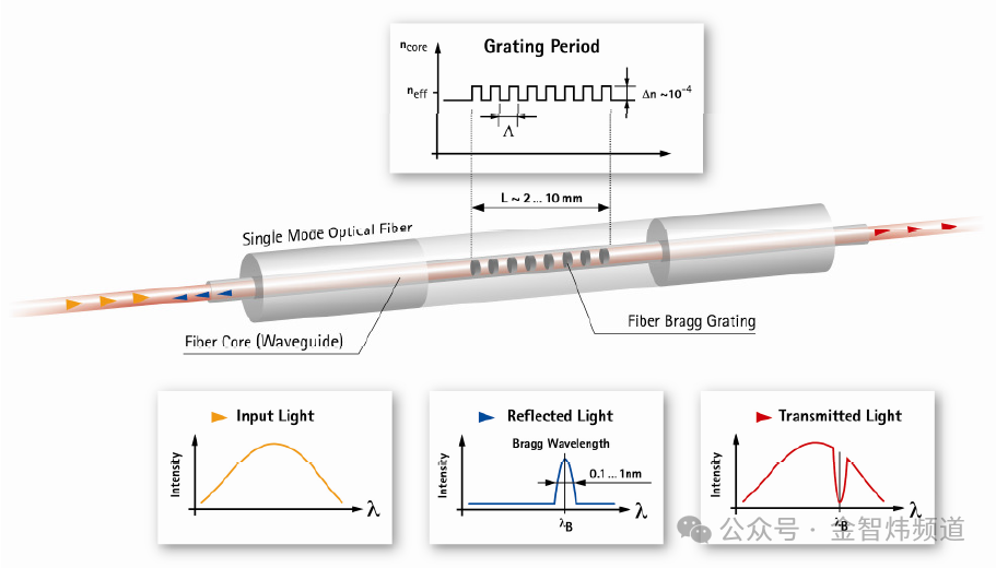
Figure 1
Figure 1 illustrates the basic principle of fiber Bragg gratings. A Bragg grating is formed by periodic modulation of the refractive index neff in the fiber core. When the wavelength of the light wave approaches the Bragg wavelength λB, it is reflected at the grating, resulting in attenuation in the transmission spectrum. Both the reflected and transmitted signals can be used for sensing analysis.
The light conducted by the fiber core is selectively reflected at the Bragg grating and undergoes coherent superposition, forming an interference pattern. Generally, measurements can be made using either the reflected spectrum of the Bragg fiber or the transmitted spectrum. However, the transmitted spectrum has a larger signal background, so HBM’s optical equipment uses reflective analysis as the standard method.
The Bragg wavelength λB is related to the grating period Λ and the effective refractive index neff, with the basic relationship given by:
(1) λB=2 neffΛ
where neff is derived from a slight periodic modulation of the refractive index ncore of the fiber core, which can be expressed as the average of the high refractive index region n1 and the undisturbed region n2:
(2) neff = (n1+n2)/2
Formation of the Grating
Periodic modulation of the refractive index can be achieved in the fiber core through pulsed laser irradiation. There are two common methods:
-
Phase Mask Writing: The laser irradiates the fiber through a periodic phase mask;
-
Talbot Interference Method: Two laser pulses create periodic interference fringes at the fiber location.
Laser irradiation induces permanent periodic changes in the refractive index within the fiber core, which may be formed by activating dopants or introducing morphological defects under high laser energy. Depending on the laser energy, they can be classified as weak gratings (reflectivity < 30%) and strong gratings (reflectivity > 90%).
For weak gratings, the main Bragg peak is usually accompanied by several side lobes. The expression for the entire reflected spectrum R(λ) is:
(3) R(λ )µ 丨sin(x(λ )) /x(λ )丨
x(λ) =pN( λ- λB )/ λB
N is the number of periods contained within the total grating length L. Figure 2 shows the measured and calculated reflection spectrum of a weak Bragg grating, with a Bragg peak reflectivity of about 15%. The side lobes are usually more than an order of magnitude lower than the main peak (>3 dB), so only the main peak is used as the effective signal.
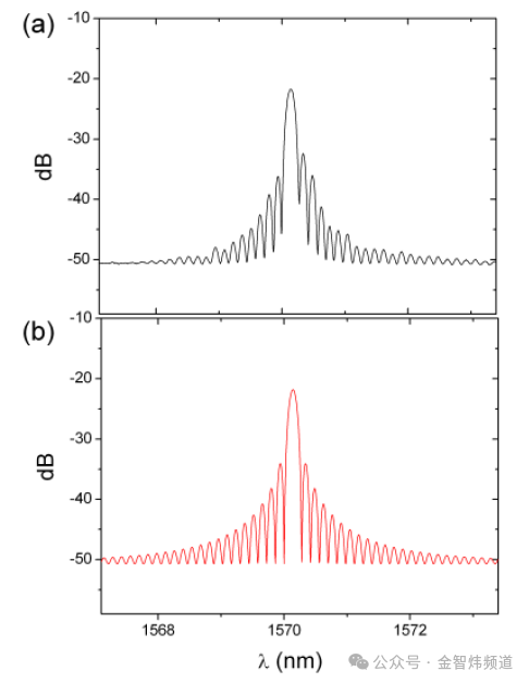 Figure 2
Sensor Parameters
HBM’s fiber sensors use weak Bragg gratings with typical parameters:
-
Grating length L ≈ 6 mm
-
Effective refractive index neff ≈ 1.46
-
Fiber core doped with germanium (for UV laser writing)
The Bragg wavelength λB is selected in the range of 1500–1600 nm (the optical communication band), where the optical loss is minimal. The corresponding grating period Λ is between 510–550 nm, so a 6 mm long grating contains more than 10,000 periods.
The fiber core diameter is 5 μm (compared to 9 μm for traditional communication fibers), which facilitates stronger bending capability (meeting total internal reflection conditions). Additionally, the Bragg grating is directly written during the fiber drawing process, followed by cladding protection, giving it high mechanical strength and the ability to measure over 1% strain.

Official Account: King-channel

Scan to Follow
Discuss Testing and Measurement Technologies