
The Design Requirements for a Perfect PLC Program
A complete PLC program is not just about making the system operational; it also requires comprehensive comments, excellent architecture, good scalability, a complete alarm protection system, and a simulation system before operation.
1. Simplicity
Keep the PLC program as simple as possible. Simplicity means using standardized program frameworks and simple instructions whenever possible.
To achieve simplicity, optimize the program structure on a large scale by simplifying the program with flow control instructions, and on a smaller scale, replace single-function instructions with more powerful ones, while also paying attention to the order of instructions.
2. Readability
The designed program must be readable. This not only helps the programmer deepen their understanding of the program for debugging but also makes it easier for others to understand and maintain the program. If necessary, it can also facilitate program promotion.
To enhance readability, the program should be as clear as possible. Pay attention to hierarchy and implement modular design, even using object-oriented methods. Utilize standard designs as much as possible.
In special cases where language programming is used, ladder diagram programming should be preferred for easier reading.
Moreover, I/O allocation should be systematic for easier memorization and understanding. If necessary, add comments. The use of internal components should also follow a pattern; do not use them arbitrarily.
Readability should be considered from the beginning of program design. This is not easy to achieve completely, as during debugging, the addition or removal of instructions and changes in the use of internal components may make a previously clear program somewhat chaotic. Therefore, leave some room for adjustments during debugging, and after debugging, tidy up the program to enhance its quality.
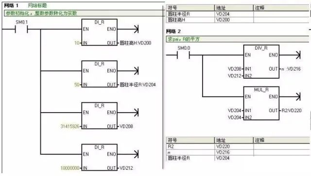
Program comments should at least cover the following aspects:
A. System comments: Copyright company and purpose of the entire program
B. Program block comments: Main purpose of this program block and author
C. Segment comments: Purpose of this segment of code
D. Variable comments: Importance is self-evident, including I/O comments and intermediate variable comments
Regarding confidentiality, I believe it should be considered in the encryption algorithm of the program or blocks, rather than using reduced comments as a clever trick.
3. Correctness
The PLC program must be correct and verified through actual work to prove it can operate correctly. This is the most fundamental requirement for a PLC program; if this cannot be achieved, nothing else matters.
To ensure correctness, instructions must be used accurately, and internal components must be used correctly. Accurate use of instructions is linked to a clear understanding of their meanings and usage conditions. If necessary, write small programs to test unclear instructions.
Some instructions may differ due to different production batches or series models of PLCs; therefore, carefully consult the programming manual.
Correct use of internal components is also crucial. For instance, some PLCs have power-off protection while others do not. Ensure that power-off protection components are used where required, and vice versa.
In summary, accurate use of instructions and correct use of internal components are fundamental requirements for ensuring the program operates correctly.
For example, Siemens’ rising and falling edges require the use of variables with memory functions as intermediate variables, such as M points or DB points; using the FC’s temp variable will cause issues.
4. Reliability
The program must not only be correct but also reliable. Reliability reflects the stability of the PLC program, which is also a basic requirement.
Some PLC programs may work correctly under normal working conditions or legal operations, but fail under abnormal conditions (such as temporary power outages followed by quick reconnection) or illegal operations (such as pressing buttons out of order or pressing several buttons simultaneously). Such programs are not very reliable or stable, which indicates poor quality.
A good PLC program can recognize abnormal working conditions and adapt to normal conditions, making it suitable for various situations. A good PLC program can reject illegal operations without leaving any “traces” and only accepts legal operations.
Interlocking is a common method to reject illegal operations, often used in relay circuits, and PLCs can inherit this method.
5. Modifiability
The program should be easy to modify.
One of the characteristics of PLCs is convenience, allowing flexible adaptation to various situations. This is achieved through modification or redesign of the program.
Redesigning the program is necessary when changing the PLC’s process requirements, which involves not only reprogramming but also reallocating I/O. In most cases, reprogramming is not required; minor modifications will suffice. This requires the program to be flexible and easy to modify.
Modifiability also implies elasticity, meaning that only minor changes are needed to alter parameters or modify actions.
6. Scalability
Many programs may be written before going on-site, but additional programs may need to be added on-site. To avoid disrupting the overall system structure, reserve some space in each functional area as a backup.
Leave enough margin in hardware, and consider manual, automatic, and semi-automatic operations when writing software, leaving space accordingly.
7. Complete Alarm System
PLC systems are often used in industrial environments, where every accident can cause varying degrees of loss. To ensure pre-accident handling or minimize losses during accidents, it is essential to emphasize the alarms and protections of the PLC, making it an important component of the system.
8. Program Simulation
To ensure the progress of on-site debugging or to demonstrate to clients, it is often necessary to conduct full automatic simulations of the program before going on-site. For this, a simulation portion must be included in the program, which is disconnected after normal on-site operation. To enable simulation functionality, the following tasks must be completed:
(1) Convert the actual PLC I/O points into intermediate variables or data block variables;
(2) Write simulation programs for each device according to process requirements.
In the process of designing PLC programs, those that meet the above requirements can be considered good programs.
PLC Program Design Specifications
1.Select the appropriate PLC model and I/O points, and choose special function modules when there are special functional requirements.
2.Familiarize yourself with the selected PLC programming instructions and compilation software.
3.Plan soft components, including internal relays, holding relays, data registers, timers, counters, etc.
4.Plan the program, generally in the order of fault extraction, fault handling, manual handling, automatic handling, and output handling. For larger projects or equipment, process them in segments or blocks by functional units. For example, in an automated production line with elevators, transfer devices, and lifting rotating devices, programming should be done in segments according to these units.
5.Before writing segmented programs, add brief segment comments explaining the function of this segment, and if necessary, indicate the corresponding process flow. The order of segmented or block programs in the overall program should generally follow the process flow for better readability.
6.Before program design, abstract the equipment to extract common factors such as stop, emergency stop, overload, over-limit, timeout, safety light curtain, collision stop, and door switches, placing them in the start loop or main control and interlock loops as a prerequisite for the entire program structure. Based on this, divide the program into two main functional areas: automatic and manual.
7.Extract common factors in the manual functional area of the program structure, such as manual control and factors that endanger equipment and personnel safety, placing them in the manual main control and interlock loops to protect, shield, and alarm manual control.
8.Extract common factors in the automatic functional area of the program structure, such as automatic, over-limit, and timeout factors, placing them in the automatic main control and interlock loops to protect, shield, and alarm equipment under automatic control. A general principle is to strictly limit equipment access while ensuring safety, and to allow more lenient restrictions on equipment output.
9.During program design, a total reset function should be designed to allow users to quickly restore normal operation in case of equipment failure. The total reset should fully consider the safety of equipment and personnel during the reset process.
10.When switching from automatic mode to manual mode, the program should clear the outputs and intermediate states from the automatic mode. Especially when using the SET instruction in automatic mode, it must be cleared with the RESET instruction in manual mode.
11.It is strictly prohibited to use dual outputs in program compilation, meaning the same output statement or output coil should not appear more than once in the program. For outputs of the same point under different mode conditions, use intermediate relays for transfer, and finally concentrate them together to the output point.
12.When using touch screens, do not program other functional aspects in the control and status areas shared by the touch screen and PLC.
13.For special modules of the PLC, check whether their control and status areas occupy working words before use. If they do, do not program these working words for other purposes.
14.PLC inputs, outputs, intermediate relays, timers, counters, data registers, etc., must have Chinese comments. Inputs and outputs should also have component name positions. For corresponding input points, it is generally assumed that peripheral switches are connected to NO contacts; those requiring NC contacts must be indicated in the comments. All comments should be clear and unambiguous, minimizing the use of vague terms.
15.After engineering debugging is completed, the final software program must be retained, and the saved file name should include project number/author/date information/version number, etc.
16.Regarding program encryption: passwords for encrypted programs must be saved in a dedicated file, indicating the corresponding username + password + permissions, and distributed to at least two people to prevent loss of the password leading to inability to open the program.
Programming Recommendations
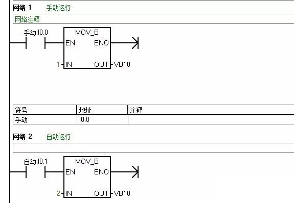
1.When the PLC and the upper computer (or touch screen) form a monitoring system, the screen often needs control modes such as “manual” and “automatic” (generally only one can be active at a time). In the program, you can use the “MOV” instruction. For example, when selecting “manual,” move constant 1 to register VB10; when selecting “automatic,” move 2 to the same register VB10. By checking the data in the register, you can determine the control mode of the system. This approach is easy to understand and avoids the complexity of interlocking programs.
2.If the program involves analog control and the read analog values have minimal error, a time filter can be used to delay for a period. If the read data has significant errors, other filtering methods, such as averaging, should be employed. Relevant materials can be consulted.
3.During program debugging (especially when modifying equipment, and your program is added to the original program), if conditions are met but the output coil does not activate, check whether your segment of the program is between such statements as JUMP/go to, etc. Another possibility is that after an interrupt, conditions are met but the output does not activate; this is usually because this segment of the program is not being scanned.
4.In sequential control programs, where one action is completed before moving to the next, using a +10+10 control mode is very convenient. The idea is to preset a register initialized to 0; when the system starts, add 10 to it, making the register 10. When the register equals 10, the first action can be performed; after completing the first action, add 10 again, making the register 20, allowing the second action to be performed. This continues, and as long as you check the data in the register, you know which action to complete. When a jump action is needed, you can add +20/+30, etc., depending on the actual needs.
Why add 10 instead of 1? Because after adding 10, if an action is inserted, you can choose any position within those 10 spare slots.
5.When designing the program, if a process fault occurs (not controlled by the control system), it is best to maintain the fault phenomenon and have visual and audible alarms until the operator resets it, so they are aware of the system fault. Otherwise, if the system stops, others may think it is a problem with your program. This is generally something to consider when designing a new system.
6.For frequently called subprograms, they can be made into sub-modules for frequent invocation.
7.Since the various steps of mechanical production require a certain amount of time during execution, and these times have certain limits, these times can be used as a reference. When the action of the step to be detected begins, start a timer, setting the timer’s preset value to be 20%-30% longer than the normal duration of that action. The timer’s output signal can be used for alarms or automatic shutdown devices. If the action time of a production machine exceeds the specified time and does not transition to the next step by the preset timer, the timer will issue a fault signal, stopping the normal working cycle program and starting the alarm or shutdown program, which is commonly referred to as over-timing protection.
8.Some safety detection switches (such as emergency stop buttons, safety light curtains, limit switches, etc.) should use normally closed (NC) inputs.
9.For safety and energy-saving considerations, design outputs to only activate when needed, stopping output once in position, rather than designing them to output continuously and only stopping when required.
10.The principle for the action of executing components should be to prefer not to move rather than to move incorrectly!
11.For single device control: each device must have soft manual/automatic switching, and during soft manual operation, it should have start/stop functionality. When switching from automatic to soft manual, the device should not stop; when switching from soft manual to automatic, the device’s start/stop depends on the automatic program.
12.Single devices (pumps, fans, and other large equipment) should run for a full 24 hours.
Click the upper right corner to share!