Overview
This article describes the virtualization support of Armv8-A AArch64, including stage 2 page table translations, virtual exceptions, and traps. It introduces some basic hardware-assisted virtualization theories and examples of how some Hypervisors utilize these virtualization features. This text will not discuss how a specific Hypervisor software operates or how to develop a Hypervisor. By reading this article, you will learn about two types of Hypervisors and how they map to Arm’s exception levels. You will be able to explain how traps work and how they are used for various emulation operations. You will also be able to describe what virtual exceptions a Hypervisor can generate and the mechanisms for generating these virtual exceptions. A certain foundation is required to understand this article, and it assumes you are familiar with the exception model and memory management of the ARMv8 architecture.
Introduction to Virtualization
Here we will introduce some fundamental theories regarding Hypervisors and virtualization. If you already have a certain foundation or are familiar with these concepts, you may skip this part. We use the term Hypervisor to define software responsible for creating, managing, and scheduling Virtual Machines (VMs).
Why is Virtualization Important?
Virtualization is a widely used technology in modern cloud computing and enterprise infrastructure. Developers use virtual machines to run multiple different operating systems on a single hardware platform to develop and test software, avoiding potential damage to the primary computing environment. Virtualization technology is very popular on servers, and most server-oriented processors need to support virtualization capabilities because virtualization can provide essential features for data center servers:
-
Isolation: Virtualization allows for the isolation of VMs running on the same physical core. This enables untrusted computing environments to share the same hardware environment. For example, two competitors can share the same physical machine without accessing each other’s data. -
High Availability: Virtualization can seamlessly and transparently migrate loads between different physical machines. This technology is widely used to migrate loads from faulty hardware platforms to other available platforms for maintenance and replacement of faulty hardware without affecting service. -
Load Balancing: To reduce hardware and power costs in data centers, it is necessary to utilize hardware platform resources as fully as possible. Balancing loads across different physical machines helps to maximize physical machine resources, reduce power consumption, and provide optimal performance for tenants. -
Sandboxing: VMs can act as a sandbox to shield applications running within them from interference from other software or prevent them from interfering with other software. For example, running specific software in a VM can prevent bugs or viruses from damaging other software on the physical machine.
Two Types of Hypervisors
Hypervisors are typically divided into two types: Type 1 (bare-metal) and Type 2 (hosted). Let’s first look at Type 2 Hypervisors. For Type 2 Hypervisors, the hosted operating system has complete control over the hardware platform and resources (including CPU and physical memory…). The following diagram illustrates a Type 2 Hypervisor.
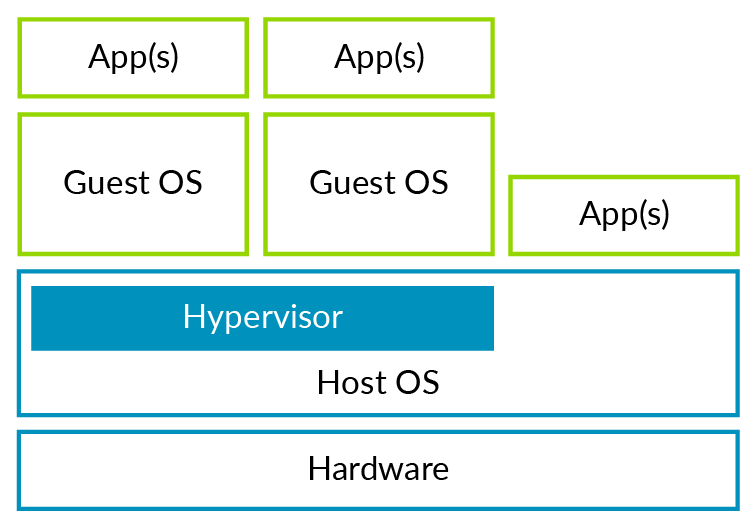
The host operating system refers to the operating system that runs directly on the hardware platform and provides the runtime environment for the Type 2 Hypervisor. This type of Hypervisor can fully utilize the host operating system’s management capabilities over the physical hardware, while the Hypervisor only needs to provide virtualization-related functions. You may have used software like Virtual Box or VMware Workstation, which are examples of Type 2 Hypervisors.
Next, let’s look at the independent Type 1 Hypervisor, as shown in the following diagram. This type of Hypervisor does not have a host operating system. It runs directly on the physical hardware, managing various physical resources while managing and running guest operating systems.
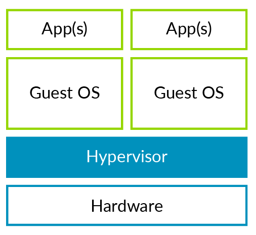
Common open-source Hypervisors like Xen (Type 1) and KVM (Type 2) belong to these two different types.
Full Virtualization and Paravirtualization
A classic definition of a virtual machine is: a virtual machine is an independent, isolated computing environment that makes the user feel like they are using a real physical machine. Although we can simulate real hardware on ARM-based hardware platforms, this is often not the most efficient approach, and we often do not do so. For example, simulating a real Ethernet device is very slow because accessing any simulated register will trap into the Hypervisor for simulation. This operation is much more costly than directly accessing physical registers. An alternative is to modify the guest operating system to make it aware that it is running in a virtual machine, allowing the Hypervisor to simulate a virtual device for the guest to use, thus achieving better I/O performance. Strictly speaking, full virtualization requires complete simulation of real hardware, resulting in poorer performance. The open-source project Xen promotes paravirtualization by modifying the core parts of the guest operating system to make it more suitable for running in a virtual environment, thereby improving performance.
Another reason for using paravirtualization is that early architectures were not designed for virtualization and had virtualization holes. Virtualization requires that all sensitive instructions or instructions accessing sensitive resources can be intercepted and simulated. For architectures with virtualization holes, a paravirtualization scheme is needed to fill in the gaps. Nowadays, most architectures support hardware-assisted virtualization, including Arm. This allows the core parts of the operating system to achieve better performance without modification. Only a few storage and network-related I/O devices still use paravirtualization schemes to improve performance, such as virtio and Xen PV Bus.
Virtual Machines (VMs) and Virtual CPUs (vCPUs)
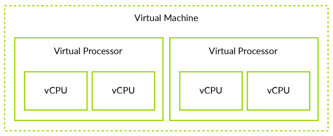
It is necessary to distinguish between virtual machines (VMs) and virtual CPUs (vCPUs). This distinction is beneficial for understanding the subsequent parts of this article. For example, a memory page can be allocated to a virtual machine, allowing all vCPUs belonging to that VM to access it. A virtual interrupt, on the other hand, is specific to a vCPU, meaning only that vCPU can receive it. The relationship between VMs and vCPUs is illustrated in the following diagram.
Note: The ARM architecture defines the term Processing Element (PE), and modern CPUs may contain multiple cores or threads. PE refers to a single execution unit. Similarly, the vCPU here should strictly be referred to as vPE.
Virtualization in AArch64
For ARMv8, the Hypervisor runs at the EL2 exception level. Only software running at EL2 or higher exception levels can access and configure various virtualization features.
-
Stage 2 Translation -
EL1/0 Instruction and Register Access -
Injecting Virtual Exceptions
The exception levels and software that can run in secure and non-secure states are shown in the following diagram:
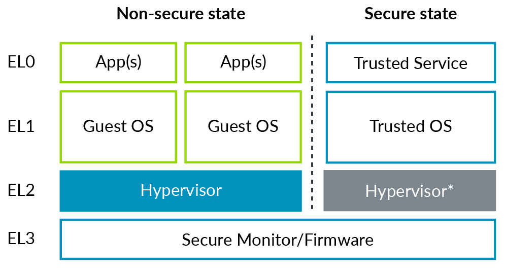
Note: The EL2 in secure state is shown in gray because the EL2 in secure state is not always available, which is a feature introduced in Armv8.4-A.
Stage 2 Translation
What is Stage 2 Translation?
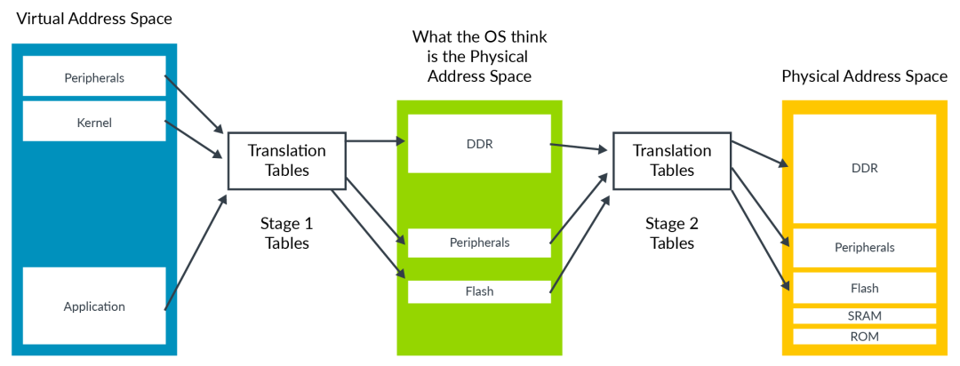
Stage 2 translation allows the Hypervisor to control the memory view of the virtual machine. Specifically, it can control whether the virtual machine can access a specific block of physical memory and where that memory block appears in the virtual machine’s memory space. This capability is crucial for the isolation and sandboxing functions of virtual machines. It ensures that a virtual machine can only see the physical memory allocated to it. To support Stage 2 translation, an additional page table is needed, which we call the Stage 2 page table. The page table translations controlled by the operating system are called stage 1 translations, which are responsible for converting virtual addresses from the perspective of the virtual machine to physical addresses from the perspective of the virtual machine. The stage 2 page table is controlled by the Hypervisor and is responsible for converting physical addresses from the perspective of the virtual machine to real physical addresses. The physical addresses from the perspective of the virtual machine are specifically referred to as Intermediate Physical Addresses (IPA) in Armv8.
The format of the stage 2 translation table is similar to that of stage 1, but some attributes are handled differently. For example, the information determining whether the memory type is normal or device is directly encoded into the table rather than queried from the MAIR_ELx register.
VMID
Each virtual machine is assigned an ID number called VMID. This ID is used to mark which specific TLB entry belongs to which VM. VMID allows different VMs to share the same TLB cache. The VMID is stored in the register VTTBR_EL2 and can be 8 or 16 bits, controlled by the VTCR_EL2.vs bit. The support for 16-bit VMIDs was introduced in armv8.1-A and is optional. It is worth noting that address translations for EL2 and EL3 do not require VMID tagging because they do not require stage 2 translations.
VMID vs ASID
TLB entries can also be tagged with ASID (Address Space Identifier). Each application is assigned an ASID by the operating system, and all TLB entries belonging to the same application share the same ASID. This allows different applications to share the same TLB cache. Each VM has its own ASID space. For example, two different VMs can simultaneously use ASID 5, but they refer to different entities. For virtual machines, VMID is usually used in conjunction with ASID.
Attribute Integration and Overriding
Both stage 1 and stage 2 mappings contain attributes such as storage type and access permissions. The Memory Management Unit (MMU) integrates the attributes from both stages into a final attribute, with the principle of choosing the more restrictive attribute. Consider the following example:
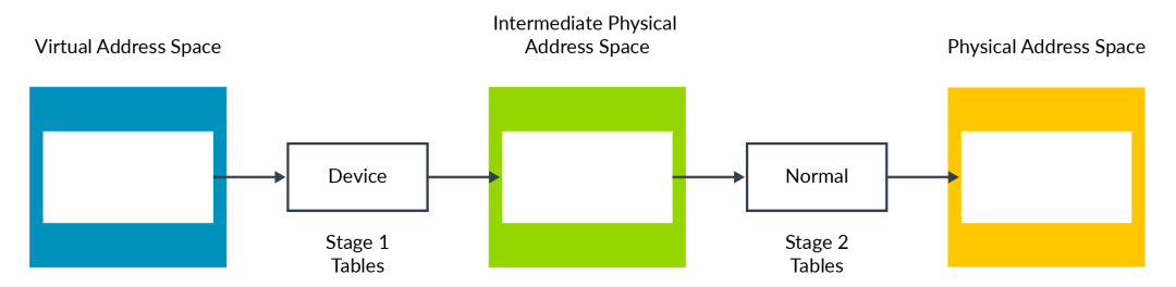
In the above example, the Device attribute is more restrictive than the Normal attribute, thus the final result is the Device attribute. The same principle applies; changing the order will not alter the final attribute.
Attribute integration generally works in most cases. However, in some instances, such as during the early boot phase of a VM, the Hypervisor may wish to change the default behavior, which can be achieved through the following register bits:
-
HCR_EL2.CD: Controls all stage 1 attributes as Non-cacheable. -
HCR_EL2.DC: Forces all stage 1 attributes to Normal, Write-Back Cacheable. -
HCR_EL2.FWB (introduced in Armv8.4-A): Uses stage 2 attributes to override stage 1 attributes instead of using the default restrictive integration principle.
Simulating MMIO
Similar to the physical address space of a physical machine, the IPA address space of a VM contains both memory and peripheral device areas. The following diagram illustrates this:
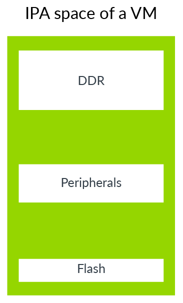
The VM uses the peripheral device area to access the physical peripheral devices it sees, which includes both passthrough devices and virtual peripheral devices. Virtual devices are fully simulated by the Hypervisor, as shown in the following diagram:
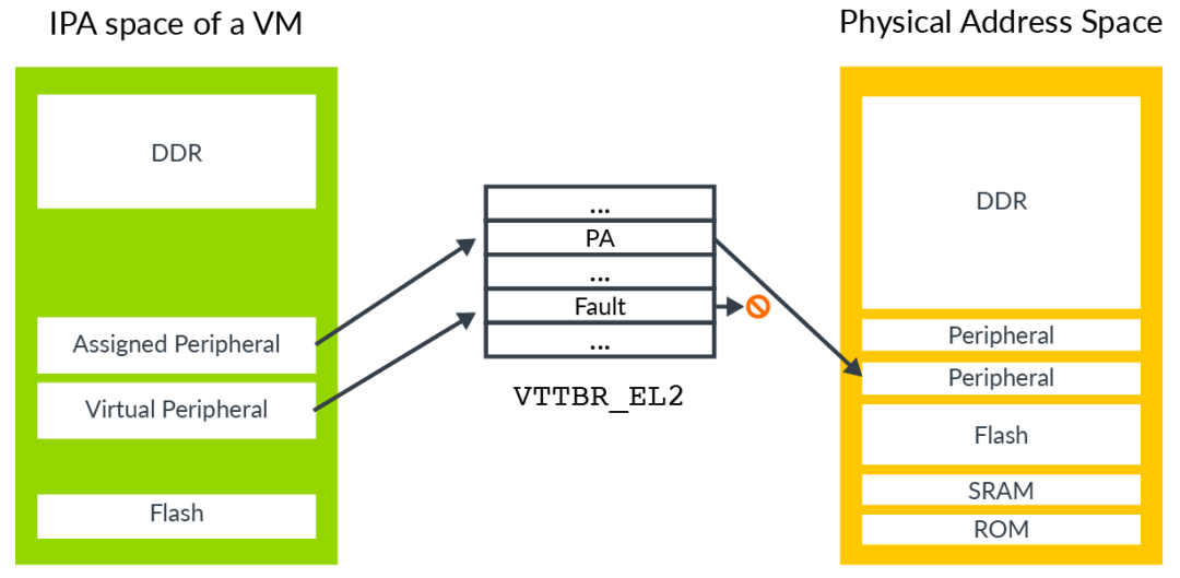
A passthrough device is directly allocated to the VM and mapped to the IPA address space, allowing software within the VM to directly access the actual physical hardware. A virtual peripheral device is simulated by the Hypervisor, with its stage 2 translation entry marked as fault. Although software in the VM appears to be directly interacting with the physical device, this access will actually result in a stage 2 translation fault, triggering the corresponding exception handler to simulate it by the Hypervisor.
To simulate a peripheral device, the Hypervisor needs to know which peripheral device is being accessed, which register of the peripheral device is being accessed, whether it is a read or write access, the length of the access, and which registers are used to transfer data.
When handling stage 1 faults, the FAR_ELx register contains the virtual address that triggered the exception. However, virtual addresses are not used by the Hypervisor; it typically does not know how the guest operating system has configured the mappings of the virtual address space. For stage 2 faults, there is a dedicated register, HPFAR_EL2, which reports the IPA address where the error occurred. The IPA address space is controlled by the Hypervisor, so it can use the information in this register to perform the necessary simulation.
The ESR_ELx register is used to report relevant information about the exception that occurred. When loads or stores to a general-purpose register trigger a stage 2 fault, the relevant exception information is provided by these registers. This information includes the length of the access and the original address or destination address of the access. The Hypervisor can use this to determine the access permissions for the virtual peripheral device. The following diagram illustrates a trapping – emulating access process:
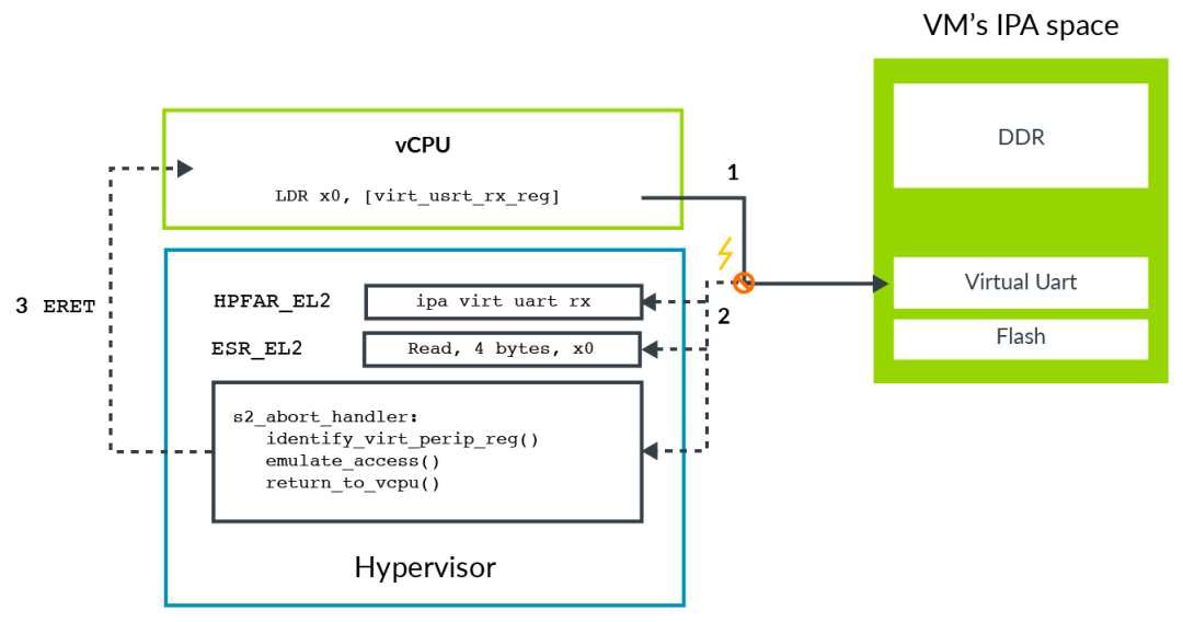
The software in the VM attempts to access a virtual peripheral device, in this case, the receive FIFO of a virtual UART. This access is blocked by the stage 2 translation, resulting in an abort exception routed to EL2.
The exception handler queries ESR_EL2 for information about the exception, such as the access length, destination register, and whether it is a load or store operation. The exception handler queries HPFAR_EL2 to obtain the IPA address where the abort occurred.
The Hypervisor simulates the relevant virtual peripheral device based on the information in ESR_EL2 and HPFAR_EL2. Once the simulation is complete, it returns to the vCPU using the ERET instruction and continues executing from the next instruction after the exception occurred.
System Memory Management Units (SMMUs)
So far, we have only considered accesses initiated by the processor. We also need to consider accesses initiated by other master devices such as DMA controllers. We need a way to extend the stage 2 mapping to protect the address space of these master devices. If a DMA controller is not using virtualization, it should look like this:
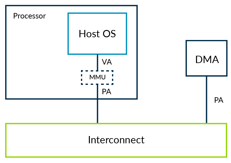
DMA controllers are usually programmed and controlled by kernel drivers. The kernel driver ensures that the memory protection principles at the operating system level are not violated, meaning that an application cannot use DMA to access memory belonging to other applications without permission.
Now let’s consider the scenario where the operating system runs in a virtual machine.
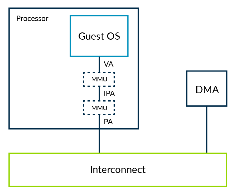
In this system, the Hypervisor isolates the address spaces of different VMs through stage 2 mappings. This is implemented based on the stage 2 mapping table controlled by the Hypervisor. However, the driver interacts directly with the DMA controller, leading to two issues:
-
Isolation: The DMA controller’s access lacks isolation between virtual machines, which undermines the sandboxing function of the virtual machines. -
Address Space: Using two-level mapping translations means that the kernel sees physical addresses (PAs) as Intermediate Physical Addresses (IPAs). However, the DMA controller still sees PAs. Therefore, the DMA controller and the kernel see different address spaces. To resolve this issue, every time a VM interacts with a DMA controller, it needs to trap into the Hypervisor to perform the necessary translations. This approach is extremely inefficient and prone to errors.
The solution is to extend the stage 2 mechanism to DMA controllers. This means that these master device controllers also need an MMU, referred to as SMMU (often called IOMMU) in Armv8.
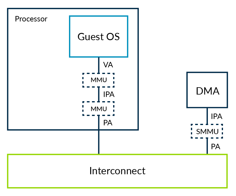
The Hypervisor is responsible for configuring the SMMU so that the physical address space seen by the DMA controller matches the physical address space seen by the kernel. This resolves the two issues mentioned above.
Trapping and Emulating Instructions
Sometimes the Hypervisor needs to simulate certain operations, such as when software running in the VM attempts to configure certain properties of the processor, such as power management or cache coherence. Typically, you would not allow a VM to configure these properties directly, as it would break isolation and affect other VMs. This requires generating an exception through trapping, allowing the Hypervisor to perform the necessary emulation in the exception handler. Armv8 includes some trap controls to help implement trapping – emulating. If trapping is configured for the corresponding operation, that operation will trap to a higher exception level when it occurs, allowing the Hypervisor to simulate it.
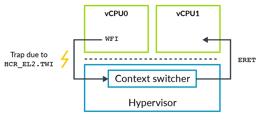
For example, executing the Wait For Interrupt (WFI) instruction causes the CPU to enter a low-power state. However, when HCR_EL2.TWI==1 is configured, executing WFI in EL0/EL1 will result in an exception to EL2. (Note: Trapping is not designed for virtualization; there are traps to EL3 and EL1 exceptions, but exceptions are crucial for virtualization implementation.)
In the case of WFI, the operating system executes the WFI instruction in an idle loop, but when the operating system in the virtual machine executes this instruction, it traps into the Hypervisor for simulation, at which point the Hypervisor typically schedules another vCPU to execute.
Register Access
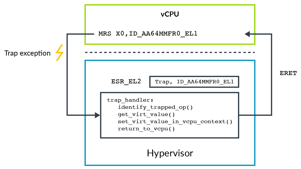
Another use of trapping – emulating is to present the values of virtual registers. For example, the register ID_AA64MMFR0_EL1 is used to report memory-related features of the processor, and the operating system may read this register to decide whether to enable or disable certain features in the kernel. The Hypervisor may present a different value to the VM than the actual physical register. How is this achieved? First, the Hypervisor needs to enable trapping for read operations on this register. Then, in the exception handling for the trap, it checks the exception-related information and performs the emulation. In the following example, a virtual value is set, and then ERET is returned.
Avoiding Traps
The overhead of trapping – emulating is significant. This operation requires trapping to EL2, then having the Hypervisor perform the necessary emulation before returning to the guest operating system. For certain registers like ID_AA64MMFR0_EL1, the operating system does not access them frequently, so the overhead of trapping – emulating is acceptable. However, for frequently accessed registers and performance-sensitive code, excessive trapping can significantly impact system performance. In such cases, we need to optimize trapping as much as possible.
-
MIDR_EL1: Contains processor type information. -
MPIDR_EL1: Affinity configuration.
The Hypervisor may want to avoid trapping every time it accesses these registers. For these registers, Armv8 provides corresponding versions that do not require trapping. The Hypervisor can pre-configure the values of these registers when entering the VM. When the VM reads MIDR_EL1 / MPIDR_EL1, it automatically returns the values of VPIDR_EL2 / VMPIDR_EL2 without trapping.
-
VPIDR_EL2: Reading MIDR_EL1 returns the value of VPIDR_EL2, avoiding trapping. -
VMPIDR_EL2: Reading MPIDR_EL1 returns the value of VMPIDR_EL2, avoiding trapping.
Note: VPIDR_EL2 / VMPIDR_EL2 do not have initialized values after a hardware reset; they must be initialized to a reasonable value by the software startup code.
Virtualization of Exceptions
Interrupts are a mechanism for hardware to notify software, and in a virtualized system, interrupt handling becomes more complex. Some interrupts are handled directly by the Hypervisor, while others are assigned to VMs and need to be handled by the handlers within the VM. Moreover, it is possible that the corresponding VM is not scheduled to run when this interrupt is received. This means we need to support handling interrupts directly in EL2, as well as a mechanism to forward received interrupts to the corresponding vCPU of the VM. Armv8 provides vIRQs, vFIQs, and vSErrors to support virtual interrupts. These interrupts behave similarly to physical interrupts (IRQs, FIQs, and SErrors), except that they can only be received when the system is running in EL0/1 and not when running in EL2/3.
Enabling Virtual Interrupts
Virtual interrupts are also controlled based on the type of interrupt. To send a virtual interrupt to EL0/1, the Hypervisor needs to set the corresponding interrupt routing bits in HCR_EL2. For example, to enable vIRQ, you need to set HCR_EL2.IMO, which means physical IRQ interrupts will be sent to EL2 while virtual interrupts will be sent to EL1. In theory, Armv8 can be configured so that VMs can directly receive physical FIQs and virtual IRQs. However, in practical applications, VMs are usually configured to only receive virtual interrupts.
Generating Virtual Interrupts
There are two ways to generate virtual interrupts:
-
Configure HCR_EL2 to generate interrupts from internal CPU cores. -
Use external interrupt controllers of GICv2 and above to generate virtual interrupts.
Let’s first look at the first mechanism, which has the following control bits in HCR_EL2:
-
VI: Configure vIRQ. -
VF: Configure vFIQ. -
VSE: Configure vSError.
Setting these bits is equivalent to sending interrupt signals to the vCPU from the interrupt controller. Like conventional physical interrupts, virtual interrupts are controlled by PSTATE. This mechanism is simple and easy to use, but has a significant drawback: the Hypervisor must simulate the relevant operations of the interrupt controller, and a series of trapping – emulating will incur performance overhead.
The second way is to use Arm’s Generic Interrupt Controller (GIC) to generate virtual interrupts. Starting from GICv2, the GIC can send physical and virtual interrupts through the physical CPU interface and the virtual CPU interface. See the diagram below:
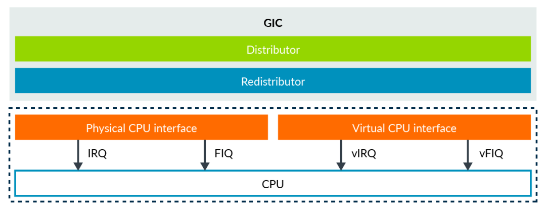
These two CPU interfaces are equivalent; the difference is that one sends physical interrupt signals, while the other sends virtual interrupt signals. The Hypervisor can map the virtual CPU interface to the VM so that the VM can communicate directly with the GIC. The advantage of this method is that the Hypervisor only needs to establish the mapping without any simulation, thus improving performance. (Note: The key to improving virtualization performance lies in optimizing traps, reducing their frequency, and optimizing processes.)
Example of Forwarding Interrupts to vCPU
The above sections introduced how virtual interrupts are enabled and generated. Let’s look at an example of forwarding an interrupt to a vCPU. Consider a physical peripheral device that is assigned to a VM, as shown in the following diagram:
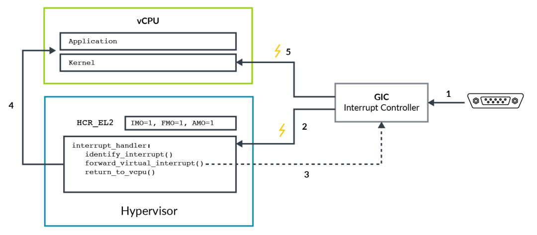
The specific steps are as follows:
-
The physical peripheral device sends an interrupt signal to the GIC. -
The GIC generates a physical interrupt exception, which may be IRQ or FIQ. Due to the configuration of HCR_EL2.IMO/FMO, these exceptions are routed to EL2. The Hypervisor discovers that this device has been assigned to a VM, so it checks which vCPU should receive this interrupt signal. -
The Hypervisor configures the GIC to send the physical interrupt to a specific vCPU in the form of a virtual interrupt. The GIC then sends vIRQ/vFIQ signals, which will be ignored if still running in EL2. -
The Hypervisor returns control to the vCPU. -
The processor runs in EL0 or EL1, and the virtual interrupt from the GIC is received (controlled by PSTATE).
The above example demonstrates how to forward a physical interrupt to a VM in the form of a virtual interrupt. If it is a pure virtual interrupt without a corresponding physical interrupt, the Hypervisor can directly inject the virtual interrupt.
Interrupt Masking
We know that the interrupt masking bits PSTATE.I, PSTATE.F, and PSTATE.A correspond to IRQs, FIQs, and SErrors, respectively. When running in a virtualized environment, the behavior of these bits is slightly different.
For example, for IRQs, setting HCR_EL2.IMO means:
-
Physical IRQ routed to EL2. -
Enable vIRQs for EL0/EL1.
This also changes the meaning of PSTATE.I masking; when running in EL0/EL1, if HCR_EL2.IMO==1, PSTATE.I applies to virtual vIRQs rather than physical pIRQs.
Clock Virtualization
In the Arm architecture, each processor has a set of general-purpose clocks. These general-purpose clocks consist of a set of comparators that compare against the system counter. When the value of a comparator is less than or equal to the system counter, a clock interrupt is generated. In the diagram below, we can see that the general-purpose clocks in the system are represented by the yellow boxed area.

The following diagram shows the timing of two vCPUs running in a virtualized system.

In a 4ms wall-clock time, each vCPU ran for 2ms. If we set the comparator of vCPU0 to generate an interrupt after 3ms of T=0, at which wall-clock time do you want the interrupt to occur? Is it at the wall-clock time of 3ms for vCPU0’s virtual time of 2ms or at the point of vCPU0’s virtual time of 3ms?
In fact, the Arm architecture supports both configurations, depending on the virtualization scheme used. Let’s see how this is implemented.
Software running on the vCPU can access the following two types of clocks:
-
EL1 Physical Clock -
EL1 Virtual Clock
The EL1 physical clock directly compares with the system counter module, using absolute wall-clock time. The EL1 virtual clock compares with a virtual counter. The virtual counter is based on the physical counter minus an offset. The Hypervisor is responsible for specifying the corresponding offset register for the currently scheduled vCPU. This way, virtual time only covers the actual running time of the vCPU.
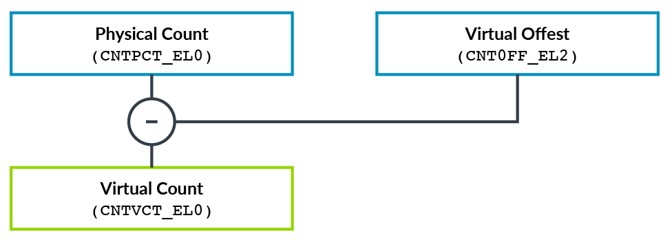
The following diagram illustrates the operation of virtual time:
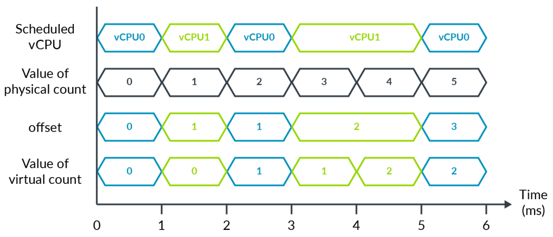
During a 6ms period, each vCPU ran for 3ms. The Hypervisor can use the offset register to adjust the vCPU’s time to its actual running time.
Virtualization Host Extensions (VHE)
The diagram shows the software stack of a Type 1 virtualization system and its corresponding exception levels, with the Hypervisor part running at EL2 and VMs running at EL0/1.
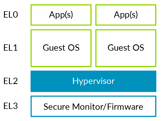
However, for a Type 2 system, its software stack and corresponding exception levels may look like the following diagram:
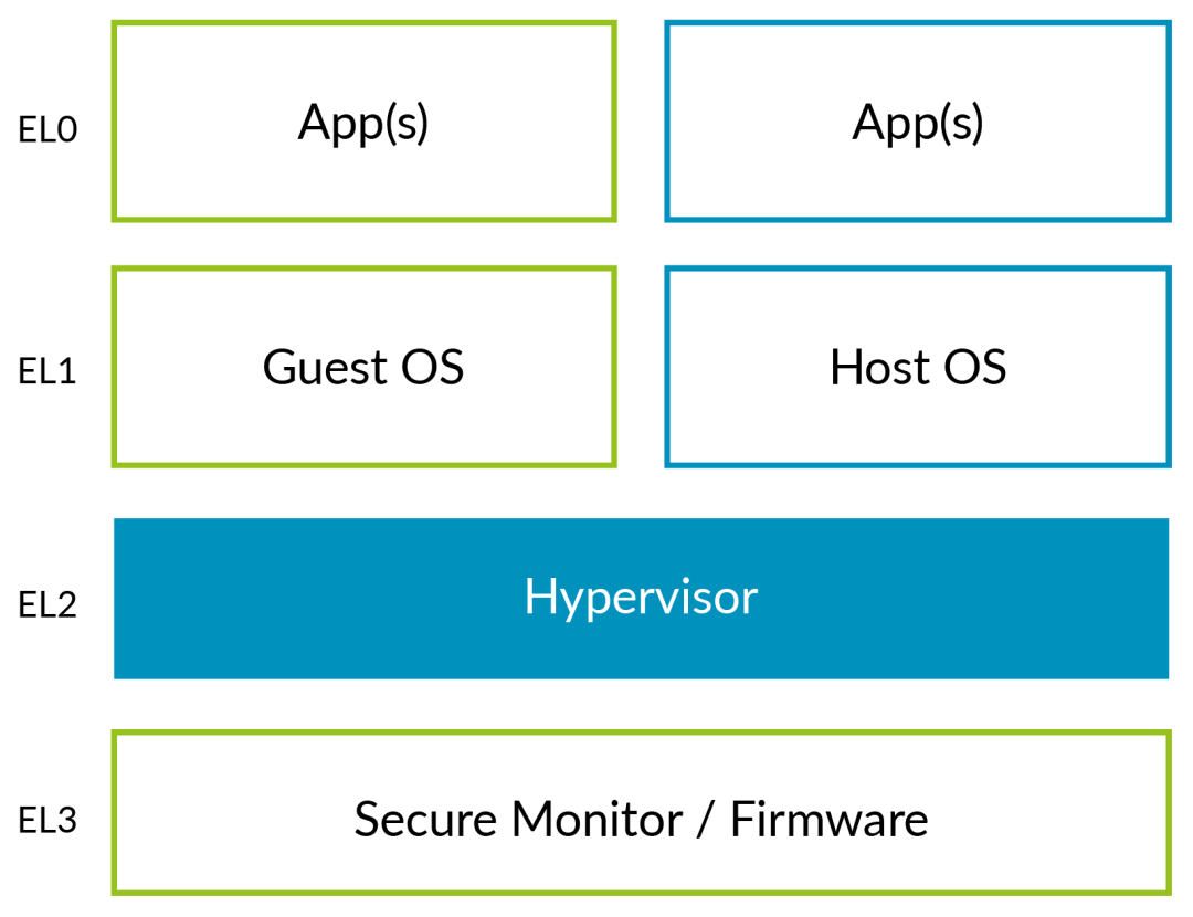
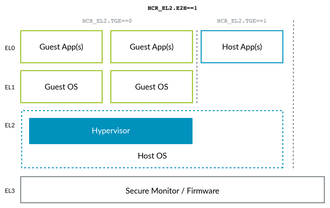
Typically, the kernel part of the host operating system runs at EL1, while the virtualization-controlling part runs at EL2. However, this design has a significant issue. Hypervisors before VHE typically needed to be designed as high-visor and low-visor components, with the former running at EL1 and the latter at EL2. This layered design can cause many unnecessary context switches during system operation, leading to considerable design complexity and performance overhead. To address this issue, Virtualization Host Extensions (VHE) were introduced. This feature, introduced in Armv8.1-A, allows the kernel part of the host operating system to run directly at EL2.
Running the Host Operating System at EL2
VHE is controlled by two bits in the system register HCR_EL2:
-
E2H: VHE Enable Bit -
TGE: When VHE is enabled, controls whether EL0 is Guest or Host
|         Running in        | E2H | TGE |
|---------------------------|-----|-----|
|Guest kernel (EL1)         |  1  |  0  |
|Guest application (EL0)    |  1  |  0  |
|Host kernel (EL2)          |  1  |  1* |
|Host application (EL0)     |  1  |  1  |
When an exception occurs and exits the VM to the Hypervisor, TGE will be initialized to 0. The software must set this bit before continuing to run the host kernel’s main code.
A typical configuration is illustrated in the following diagram:
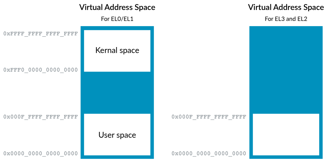
Virtual Address Space
Before the introduction of VHE, the virtual address space of EL0/1 looked like this. EL0/1 is divided into two areas, with the upper part being the kernel space and the lower part being the user space. EL2 has only one space, as the Hypervisor typically does not need to run applications, so there is no need to divide the kernel and user space. Similarly, the virtual address space of EL0/1 supports ASID, but EL2 does not need to support it.
After the introduction of VHE, EL2 can run operating system code directly. Therefore, support for address space division and ASID is required. This is also resolved by setting HCR_EL2.E2H.
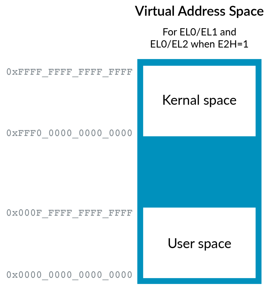
When running in EL0, HCR_EL2.TGE controls whether to use the EL1 or EL2 space; when the application runs in the Guest OS (TGE==0), the former is used, and when running in the Host OS (TGE==1), the latter is used.
Redirecting Register Access
In addition to using different address space mappings, VHE also needs to address the issue of register access. The kernel running in EL2 will still attempt to access *_EL1 registers. To run the unchanged kernel, we need to redirect EL1 registers to EL2. Once you set E2H, this will be implemented by hardware.

However, redirection can introduce a new issue, as the Hypervisor may access the actual EL1 registers in certain situations, such as during task switches. To resolve this issue, the Arm architecture introduces a new aliasing mechanism, with names ending in _EL12 or _EL02. For example, you can access TTBR0_EL1 in EL2 when ECH==1.

Exceptions
Typically, the system registers HCR_EL2.IMO/FMO/AMO can be used to control whether physical exceptions are routed to EL1 or EL2. When running in EL0 and TGE==1, the routing bits in HCR_EL2 will be ignored, and all physical exceptions (except those controlled by SCR_EL3, which will be routed to EL3) will be routed to EL2. This is because applications running in the Host OS are part of the Host OS, which runs at EL2.
Nesting Virtualization
The Hypervisor can run within a VM, known as nested virtualization.
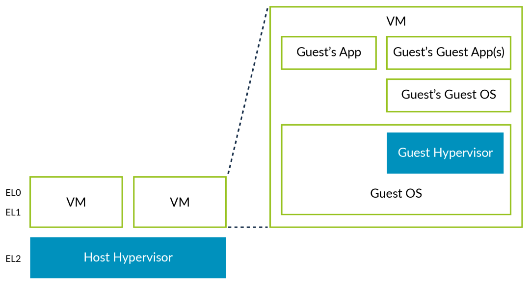
The first Hypervisor is referred to as the Host Hypervisor, while the Hypervisor running within the VM is called the Guest Hypervisor.
Prior to Armv8.3-A, the Guest Hypervisor could run at EL0. However, this design required extensive software simulation, making software development difficult and performance poor. Armv8.3-A added several new features that allow the Guest Hypervisor to run at EL1. Some new features introduced in Armv8.4-A make this process more efficient, although the Host Hypervisor still needs to participate in some additional work.
Guest Hypervisor Access to Virtualization Control Interfaces
We do not want the Guest Hypervisor to directly access the virtualization control interfaces, as this would undermine the sandboxing mechanism of the VM, allowing the virtual machine to see information about the Host platform. When the Guest Hypervisor runs at EL1 and accesses the virtualization control interfaces, new control bits in HCR_EL2 can trap these operations into the Host Hypervisor (EL2) for simulation.
-
HCR_EL2.NV: Enable hardware-assisted nested virtualization. -
HCR_EL2.NV1: Enable additional operations that require trapping. -
HCR_EL2.NV2: Enable redirection to memory. -
VNCR_EL2: When NV2==1, points to a structure in memory.
Armv8.3-A added NV and NV1 control bits. Previously, the behavior of accessing *_EL2 registers from EL1 was undefined and typically resulted in an EL1 exception. The NV and NV1 control bits allow these accesses to be trapped to EL2. This enables the Guest Hypervisor to run at EL1 while the Host Hypervisor running at EL2 simulates these operations. NV will also cause EL1 to execute ERET, trapping into EL2.
The following diagram illustrates how the Guest Hypervisor creates and starts virtual machines:
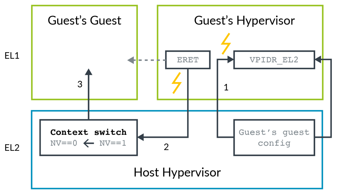
-
Accessing *_EL2 registers from EL1 will cause the Guest Hypervisor to trap into EL2. The Host Hypervisor records the configuration related to the Guest Hypervisor. -
The Guest Hypervisor attempts to enter its created virtual machine, at which point the ERET instruction will trap into EL2. -
The Host Hypervisor sets the related registers based on the Guest Hypervisor’s configuration to start the VM, clears the NV bits, and finally enters the Guest Hypervisor’s created Guest.
Using this method, any access by the Guest Hypervisor to *_EL2 registers will result in trapping. Switching operations such as task switches, vCPU switches, and VM switches will access many registers, and each trap will lead to exceptions entering and returning, causing significant performance issues due to trapping – emulating. (Recall from earlier content, the key to improving virtualization performance lies in optimizing traps, reducing their frequency, and optimizing processes). Armv8.4-A provides a better solution; when NV2 is set, accessing *_EL2 registers from EL1 will be redirected to a memory area. The Guest Hypervisor can read and write to this register area multiple times without trapping. Only when finally executing ERET will it trap into EL2. The Host Hypervisor can then extract the relevant configuration from this memory area and perform related operations on behalf of the Guest Hypervisor.
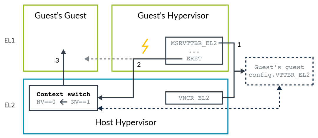
-
Accessing *_EL2 registers from EL1 will be redirected to a memory area, the address of which is specified by the Host Hypervisor in VNCR_EL2. -
The Guest Hypervisor attempts to enter its created virtual machine, at which point the ERET instruction will trap into EL2. -
The Host Hypervisor extracts configuration information from memory, sets related registers to start the VM, clears the NV bits, and finally enters the Guest Hypervisor’s created Guest.
This improved method reduces the number of traps to the Host Hypervisor, thereby enhancing performance.
Virtualization in the Secure World
Virtualization extensions were first introduced in Armv7-A. In Armv7-A, the Hyp mode is equivalent to EL2 in AArch32 and only exists in the non-secure world. As an optional feature, Armv8.4-A adds support for EL2 in the secure world. Processors that support secure world EL2 must configure the SCR_EL3.EEL2 bit under EL3 to enable this feature. Only after setting this bit can the virtualization features in the secure state be used.
Before secure world virtualization, EL3 was typically used to run secure state switching software and platform firmware. However, from a design perspective, we want to minimize the software running in EL3, as the simpler it is, the more secure it will be. Secure state virtualization allows us to move platform firmware to run in EL1, isolating the platform firmware from the trusted operating system kernel through virtualization. The following diagram illustrates this concept:
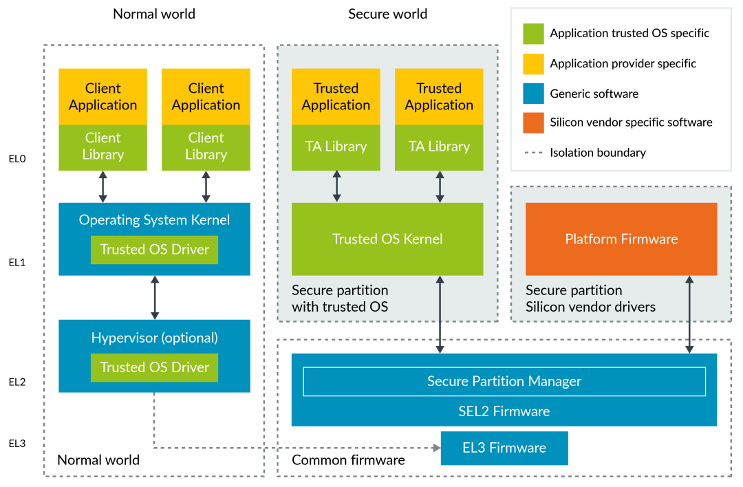
Secure EL2 and Two IPA Spaces
The Arm architecture defines two physical address spaces: secure world and non-secure world. In the non-secure state, the output of stage 1 translations is always non-secure, so only one IPA space is needed for stage 2. However, for the secure world, the output of stage 1 may be either secure or non-secure. The NS bit in the stage 1 translation table controls whether secure or non-secure addresses are used. This means that in the secure world, two IPA address spaces are needed.
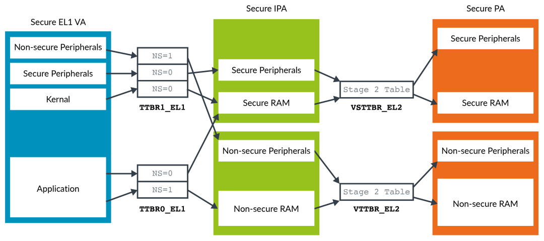
Unlike the stage 1 table, the stage 2 translation table does not have an NS bit. Because for a specific IPA space, it must be either all secure addresses or all non-secure addresses, so only one register bit is needed to determine the IPA space. Generally, non-secure addresses remain non-secure after stage 2 translation, and secure addresses remain secure after stage 2 translation.
Overheads of Virtualization
The overhead of virtualization primarily arises from the need to save and restore registers during switches between the virtual machine and the Hypervisor. In an Armv8 system, at least the following registers need to be handled:
-
31 x 64-bit general-purpose registers (x0…x30) -
32 x 128-bit floating-point/SIMD registers (V0…V31) -
Two stack registers (SP_EL0, SP_EL1)
Using LDP and STP instructions, the Hypervisor needs to execute 33 instructions to store and restore these registers. The final overhead of virtualization depends not only on the hardware but also on the design of the Hypervisor.