When working on PLC projects, many people rush to open programming software as soon as they receive a notification, eager to list I/O and write programs—this is actually a misconception. Electrical design particularly emphasizes “closed-loop thinking”; from project initiation to final implementation, every step must be interconnected. One cannot skip the critical preparatory stages nor overlook the post-project review.In the first few years of learning technology, the focus is on individual technical capabilities; however, once one can independently undertake projects, the emphasis shifts to a holistic understanding of the entire process.Here, we will detail how to make the process of conducting PLC projects more standardized and regulated, allowing electrical newcomers to quickly get started with PLC projects and avoid years of detours.1. Gather Customer RequirementsThrough 3D diagrams: The 3D diagrams are created by our internal mechanical engineers, which show the product’s dimensions, the movements of various components, the stroke of moving parts, motor power, and the functions to be achieved. Understanding these details will prevent mistakes in selecting electrical components and determining installation locations later on.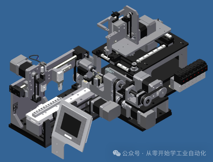 Through technical agreements: Technical agreements are generally discussed between the project department and mechanical engineers with the client before project initiation. Our electrical design typically comes in relatively late, so we need to clarify the equipment’s efficiency in terms of UPH (units processed per hour), required precision, protection level (IP rating), whether there is a host computer, barcode scanner, brand requirements, and program or touchscreen interface requirements. These are hard indicators that will affect later acceptance and cannot be vague.2. Coordinate with Mechanical DesignInitially, we need to get involved early in the design phase to understand the 3D diagrams. Once the mechanical engineer completes the 3D design, we need to verify it with them.First, we check the specifications, confirming the number of input points, output points, and axes (whether the axes are servo-driven or stepper-driven), and perform power calculations.Next, we discuss the machine’s actions. For example, in a screw locking machine, we need to understand the steps from product feeding, positioning, scanning, screwing, to discharging. Each action must be clearly communicated with the mechanical engineer.Finally, we need to discuss how to install electrical components such as sensors, solenoid valves, and motors. We will design the circuit and pneumatic layout of the machine, along with usage notes and requirements for some electrical components. We should advise the mechanical team on certain aspects, such as ensuring there is enough space for sensors to be installed without being obstructed by mechanical parts; the motor base must be sturdy enough to withstand vibrations; and there should be designated paths for wires to avoid damage from moving mechanical parts. This proactive communication can reduce the number of issues we face during later debugging.3. Coordinate with Software DesignBefore starting to write programs, we need to clarify with the software design team how the electrical and software components will interact throughout the device’s operation. For instance, we need to determine how the results from detection instruments will be transmitted to the software, how commands from the software will interact with the PLC, and how signals will be communicated in case of issues. It is best to create an interaction flowchart, and once both parties confirm the process, we can begin writing the program to avoid having to modify it halfway through due to unimplemented functions, which would inadvertently increase debugging time and labor costs.
 4. Electrical DesignOnce the preliminary work is sufficiently prepared, we can begin the electrical design work. Electrical design is not just about jumping straight into writing PLC programs and debugging. In larger companies, this may be subdivided, but in smaller companies, it is generally a “one-stop” service. It is beneficial to have a broad skill set, so let’s explore this together.I/O Table (Inputs, Outputs, Analog Signals, Axes): List the components corresponding to the input and output points, their functions, what devices the analog signals connect to, their measurement ranges, the model of each axis, and how they are controlled.Power Calculation: Calculate the total power of all electrical components to select appropriate power supplies, circuit breakers, and wire gauges, ensuring they can handle the load without burning out.Electrical Schematics (System Configuration Diagram, Control Board Layout, Circuit Diagram, Pneumatic Diagram): The system configuration diagram shows how the electrical modules are connected; the control board layout diagram plans how components are arranged on the board; the circuit diagram clarifies how wires are connected and how they function; the pneumatic diagram explains how pneumatic components are connected and controlled.Electrical Assembly SOP: Specify how electrical components should be installed, how wires should be connected, and how to label wires, ensuring that assembly personnel can follow these guidelines without making mistakes.PLC & Host Computer Communication Protocol: Define how the PLC and host computer will communicate, what format will be used to transmit data, and which addresses correspond to which information.Electrical Standard Parts Bill of Materials (Electrical BOM): List all electrical standard parts’ models, specifications, quantities, and sources for procurement. It is crucial to be accurate and not just write model numbers or quantities, as missing a letter in a model number can lead to errors.PLC Program: Write initialization, reset, manual, automatic, and alarm programs according to the control logic of the device, typically following the company’s program templates and styles.Touchscreen Program: Develop the main interface, manual interface, parameter settings interface, user management interface, and I/O monitoring interface, usually based on company templates.This is our core task, and it must be completed with care and thorough preparation so that once the machine is assembled and powered on, we can begin debugging immediately.5. Debugging During the Design PhaseBefore the first power-up, confirm: Measure the 220V or 380V AC power supply, and the 24V or 48V DC power supply to ensure the voltages are accurate. Also, check for any leakage to ground. Only after confirming these can we power on the system. During power-up, be cautious of sudden movements from motors and cylinders, and ensure personnel are out of the range of moving parts.During the first power-up process: First, supply air, then power! We check the pneumatic system for leaks; if there are none, we can start powering on. Powering on should be done gradually: first, turn off all circuit breakers, then turn them on one by one in order, checking if the indicator lights on each component are lit, and listen for any unusual sounds or smells. If there are issues, cut the power immediately. Never turn on all power at once, as it may be too late to react to any abnormalities.Download the program or servo parameters: Upload the prepared PLC program, touchscreen program, and servo parameters.Test I/O points: Test each input and output point one by one to ensure that pressing a button or moving a sensor elicits the expected response.Debug manual actions: Test the manual control of the servo motor for start/stop and forward/reverse operation, ensure the cylinder extends and retracts smoothly, and adjust the cylinder sensors, servo limits, and origin settings.Debug individual modules and interlinked debugging: First, debug each module individually, referring to modules such as the feeding module, scanning module, positioning module, screw locking module, and discharging module. After debugging each module, we will link them together to allow the entire device to run empty or with materials. We will then let the device run empty for a certain period to age it before proceeding to FAT for shipment.6. On-Site Debugging with the CustomerAfter shipment, we need to follow up to the customer’s site for debugging, as many customer products are easier to debug on-site. Here, we will mainly discuss single machine debugging, as debugging an entire line may differ slightly. The steps are as follows:Device positioning: Once the equipment is brought to the customer’s workshop, it must be positioned correctly, leveled, and aligned with adjacent machines. For large equipment, this may involve disassembly and reassembly.Powering on: Connect to the customer’s power supply, check the grounding, and once confirmed, power on and supply air.Single machine empty run: Run the equipment without materials to check if all components operate normally and to identify any potential issues that may have arisen during transport or disassembly.Single machine product debugging: Run the machine with products to see if it operates smoothly. This step can be challenging, particularly with sensors, scanning, and positioning.Front and rear interlinked debugging: Connect the equipment to the machines before and after it to check if the interlinked signals are correct, verify wiring, and ensure the logic is sound.Trial production: Once the single machine runs correctly, connect it to the adjacent machines for small batch production trials to check if the equipment’s efficiency and product quality meet requirements, ensuring the entire line can flow products smoothly. The subsequent process involves ramping up production capacity according to the production and debugging plan.At this point, our electrical design is nearing completion, with all parameters meeting the client’s technical agreement requirements. The next step is to hand over to the after-sales team for ongoing support.
 7. Project SummaryAfter debugging is complete, we need to summarize the equipment design process and prepare acceptance documentation for the client to facilitate acceptance.Acceptance documentation organization: Prepare the equipment user manual, detailing operation and precautions; maintenance manual, specifying maintenance schedules and key points; list of consumables, including models and replacement timelines for commonly used parts; troubleshooting manual, outlining methods for addressing faults; electrical schematics for reference during repairs, etc.Project documentation summary: Organize the I/O table, electrical schematics, electrical assembly SOP, PLC & host computer communication protocol, electrical BOM, PLC program, touchscreen program, servo parameters, scanner parameters, debugging progress table, and issue log. This documentation will serve as a reference for similar projects in the future.At this point, the entire project development and design process is complete. While there are still some details not mentioned, completing these seven major steps constitutes a relatively smooth development process. The review phase can be integrated into the coordination phase. Friends, if you have any suggestions, feel free to leave comments for discussion. Those in need can bookmark this for future reference.