
Today, I bring you the wiring methods for sensors and PLCs, with twenty wiring diagrams. Isn’t that super rich? Let’s take a look!
1
Overview
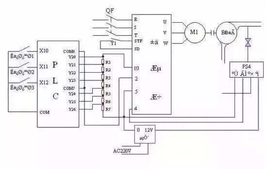
The digital input interface of the PLC is not complicated. To enhance its anti-interference capability, PLCs use optocouplers to isolate the input signals from the internal processing circuits. Therefore, the signal at the input end merely drives the internal LED of the optocoupler, which is received by the phototransistor of the optocoupler, allowing reliable transmission of external input signals.
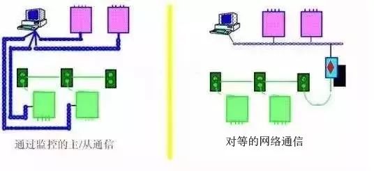
Currently, PLC digital input ports are generally divided into single-ended common point and dual-ended inputs. Due to these differences, users need to understand the wiring methods when selecting external sensors to correctly use the sensors with the PLC, laying a foundation for later programming and system stability.
2
Input Circuit Types
1. Classification of Input Types
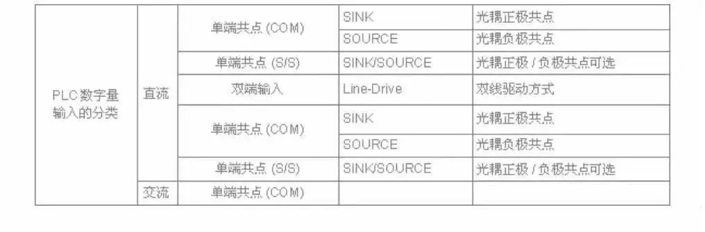
The digital input terminals of the PLC are classified by power supply into DC and AC. According to the input interface classification, there are single-ended common point inputs and dual-ended inputs. Single-ended common point connected to the positive terminal of the power supply is called SINK (sink current), while single-ended common point connected to the negative terminal of the power supply is called SRCE (source current).
2. Overview of Terms
SINK leakage type allows current to flow out from the input end, so the input end can be connected to the negative terminal of the power supply, indicating that the internal optocoupler is single-ended common point connected to the positive terminal of the power supply and can connect to NPN-type sensors.
SOURCE type allows current to flow into the input end, so the input end can be connected to the positive terminal of the power supply, indicating that the internal optocoupler is single-ended common point connected to the negative terminal of the power supply and can connect to PNP-type sensors.
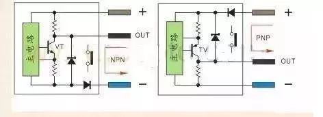
Proximity switches and photoelectric switches with three or four wire outputs are divided into NPN and PNP outputs. When there is no detection signal, the NPN proximity switch and photoelectric switch output high level (with respect to the internal pull-up resistor). When there is a detection signal, the internal NPN transistor conducts, and the switch output is low level.
When there is no detection signal, the PNP proximity switch and photoelectric switch output low level (with respect to the internal pull-down resistor). When there is a detection signal, the internal PNP transistor conducts, and the switch output is high level.
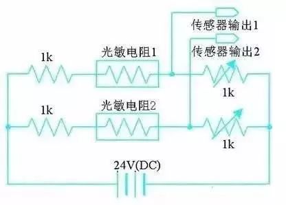
The above situations are only for sensors that are in a normally open state.
3. Configuration Types by Power Supply
(1) DC Input Circuit
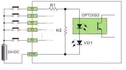
As shown in Figure 1, the DC input circuit requires external input signal components to be passive dry contacts or active DC non-contact switch contacts. When the external input component connects to the positive terminal of the power supply, current flows through R1, the LED inside the optocoupler, VD1 (interface indicator), to the COM terminal to form a loop. The receiving tube inside the optocoupler receives the signal from the external component, transmitting it to the internal processing. This interface method powered by DC is called a DC input circuit;
DC power can be provided internally by the PLC or externally supplied to the external input signal components. R2 in the circuit serves to bypass the current of the LED inside the optocoupler, ensuring that the LED of the optocoupler is not turned on by the static leakage current of the two-wire proximity switch.
(2) AC Input Circuit
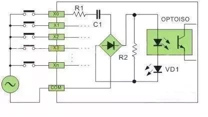
As shown in Figure 2, the AC input circuit requires external input signal components to be passive dry contacts or active AC non-contact switch contacts. The distinction from the DC interface is that a step-down circuit and bridge rectification circuit are added before the optocoupler. After the external component connects to the AC power supply, the current flows through R1, C2 through the bridge rectifier, converting it into reduced voltage DC. The subsequent circuit principle is consistent with that of DC.
AC PLC is mainly suitable for relatively harsh environments and situations where wiring technology does not change much; for example, proximity switches can directly replace the original travel switches with AC two-wire.
4. By Port Type
(1) Single-ended Common Point (Comcon) Digital Input Method
To save input terminals, the structure of single-ended common point input is to connect one end of all input circuits (optocouplers) inside the PLC to a common internal terminal marked as COM. The other end of each input circuit connects to its corresponding input terminals X0, X1, X2, ….
Common points with N single-ended inputs can perform N digital inputs (N+1 terminals), so we call this structure “single-ended common point” input. Users must also do the same when wiring external digital input components, connecting one end of all input components together, called external common line for input components; the other end connects to the PLC input terminals X0, X1, X2, ….
SINK input method can connect to NPN type sensors, i.e., the X terminal is connected to the negative terminal.
SRCE input method can connect to PNP type sensors, i.e., the X terminal is connected to the positive terminal.
(External input components can be button switches, travel switches, reed switches, Hall switches, proximity switches, photoelectric switches, light curtain sensors, relay contacts, contactor contacts, and other switch elements.)
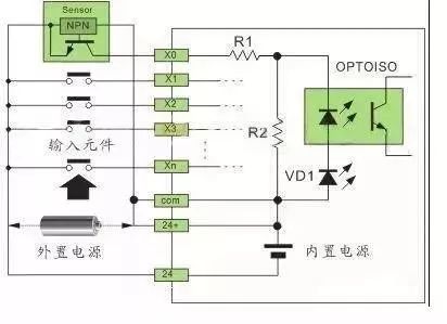
(2) SINK (sink current) Input Method ● Single-ended Common Point SINK Input Wiring (internal common point terminal COM→24V+, external common line→24V-). As shown in Figure 3:
(3) SRCE (source current) Input Method
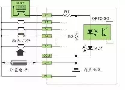
● Single-ended Common Point SRCE Input Wiring (internal common point terminal COM→24V-, external common line→24V+). As shown in Figure 4:
(4) SINK/SRCE Switchable Input Method
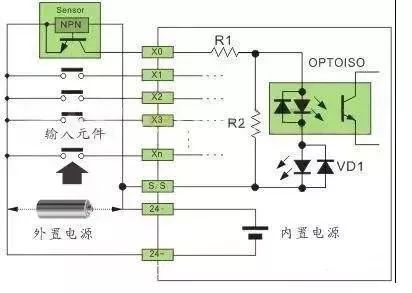
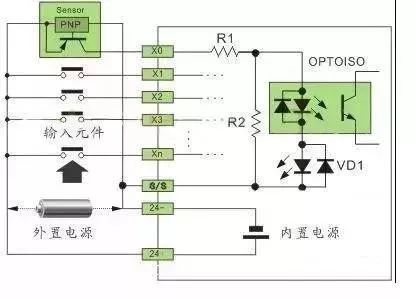
The S/S terminal differs from COM in that COM is fixedly connected to either the positive or negative terminal of the internal power supply, while the S/S terminal is non-fixed and can be connected to either the positive or negative terminal of the internal or external power supply as needed.
● Single-ended Common Point SINK Input Wiring (internal common point terminal S/S→24V+, external common line→24V-).
● Single-ended Common Point SRCE Input Wiring (internal common point terminal S/S→24V-, external common line→24V+).
(5) When there are many active input components (Hall switches, proximity switches, photoelectric switches, light curtain sensors, etc.) and high power consumption that the built-in power supply of the PLC cannot meet, an external power supply needs to be configured. Depending on the requirements, a 24VDC switch power supply of a certain power can be configured. The external power supply should not be connected in parallel with the built-in power supply. According to the characteristics of COM and external common lines, in the SINK (sink current) input method, the external power supply connects to the positive terminal of the built-in power supply; in the SRCE (source current) input method, the external power supply connects to the negative terminal of the built-in power supply.
(6) A simple way to determine SINK (sink current) input method is to short circuit the Xn terminal to the negative terminal. If the interface indicator lights up, it indicates that it is SINK input method. The common positive optocoupler can connect to NPN type sensors. For SRCE (source current) input method, short circuit the Xn terminal to the positive terminal. If the interface indicator lights up, it indicates that it is SRCE input method. The common negative optocoupler can connect to PNP type sensors.
(7) For two-wire switch inputs, if they are passive contacts, the SINK and SRCE should be connected according to the input component connection method shown above. For two-wire proximity switches, the polarity of the proximity switch needs to be determined for correct connection. Some of our company’s two-wire LJK series proximity switches can also connect to interfaces without polarity; see the attached product manual for details.
(8) High-speed Dual-ended Input Circuit
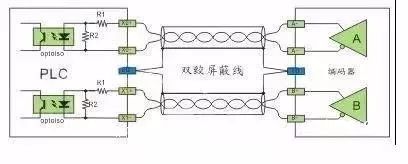
Mainly used for hardware high-speed counters (HHSC) input, with an interface voltage of 5VDC. To ensure high speed and high noise resistance, a dual-line drive method (Line-Drive) is usually adopted. If the working frequency is not high and the noise is low, a 5VDC single-ended SINK or SRCE connection can be used, with a series current-limiting resistor converted into a 24VDC single-ended SINK or SRCE connection.
(9) Dual Input Terminal Dual Line Drive Method (Line-Drive)
(10) 5VDC Single-ended SINK or SRCE Connection Method
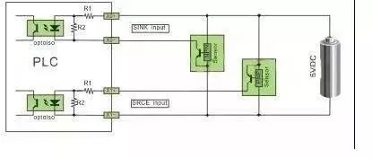
(11) 24VDC Single-ended SINK or SRCE Connection Method
Note: For sensors powered by 24VDC, a current-limiting resistor must be connected in series in the input circuit. R1 is 10Ω and R2 is 2KΩ. If the current-limiting resistor is not connected, it will burn out the interface circuit, and the value of the current-limiting resistor should be 2.7KΩ.
3
External Input Components
1. Passive Dry Contacts (Button Switches, Travel Switches, Reed Magnetic Switches, Relay Contacts, etc.)
Passive dry contacts are relatively simple and easy to wire. There is no polarity of the power supply, voltage drop, and other factors. The input components in Figure 3-6 are of this type. Here, I will not repeat the introduction.
2. Active Two-Wire Sensors (Proximity Switches, Active Reed Magnetic Switches)
Active two-wire proximity switches are divided into DC and AC. The characteristic of this sensor is that it has two wires. After the output end of the sensor is turned on, a holding voltage is required to maintain the circuit’s normal operation, usually a voltage drop of 3.5-5V, with a static leakage current of less than 1mA, which is a crucial indicator; if it is too large, the optocoupler at the PLC’s input end will conduct when there is no detection signal. Our company’s LJK series two-wire proximity switches control the static leakage current between 0.35-0.5mA, suitable for various types of PLC.
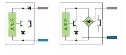
DC two-wire proximity switches are divided into diode polarity protection and bridge rectification polarity protection. The former requires attention to polarity when connecting to the PLC, while the latter does not require attention to polarity. Active reed magnetic switches are mainly used for position detection on cylinders. Since a signal indication is required, there is an internal bidirectional diode circuit, so polarity does not need to be considered; AC two-wire proximity switches also do not require attention to polarity. As shown in Figure 10:
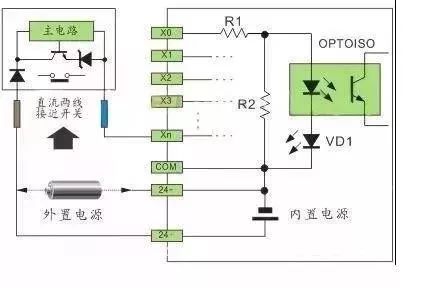
(1) Single-ended Common Point SINK Input Wiring (internal common point terminal COM→24V+, external common line→24V-). As shown in Figure 11:
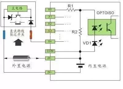
(2) Single-ended Common Point SRCE Input Wiring (internal common point terminal COM→24V-, external common line→24V+). As shown in Figure 12:
(3) S/S terminal connection method refers to Figures 5-6 and 11-12.
3. Active Three-Wire Sensors (Inductive Proximity Switches, Capacitive Proximity Switches, Hall Proximity Switches, Photoelectric Switches, etc.) Active three-wire proximity switches and photoelectric switches use transistors for output. Therefore, the sensors are divided into NPN and PNP outputs. Some products are four-wire, with double NPN or double PNP, just the opposite state; there are also NPN and PNP combined four-wire outputs.
NPN type when the sensor has a detection signal VT conducts, the current flows to the negative terminal from the output end OUT, and the output end OUT potential approaches the negative terminal, usually referred to as high level turning into low level.
PNP type when the sensor has a detection signal VT conducts, the current flows from the positive terminal to the output end OUT, and the output end OUT potential approaches the positive terminal, usually referred to as low level turning into high level.
The resistance at the emitter of the transistor in the circuit is a short-circuit protection sampling resistor of 2-3Ω, which does not affect the output current. The resistance at the collector of the transistor is a pull-up and pull-down resistor, providing output potential, facilitating the circuit of the level interface. Another type of output from the transistor collector is open-collector output, which does not connect to pull-up and pull-down resistors.
Simply put, when the transistor VT conducts, it is equivalent to conducting a contact, as shown in Figure 13:
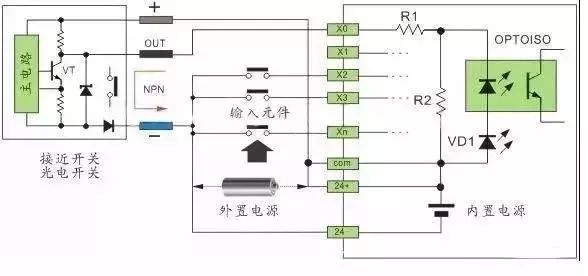
(1) Single-ended Common Point SINK Input Wiring (internal common point terminal COM→24V+, external common line→24V-). As shown in Figure 14:
(2) Single-ended Common Point SRCE Input Wiring (internal common point terminal COM→24V-, external common line→24V+). As shown in Figure 15:
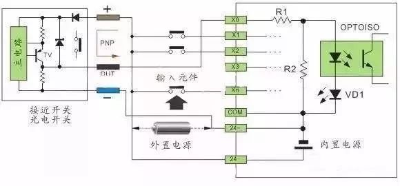
(3) S/S terminal connection method refers to Figures 5-6, 11-12, and 14-15.
The diversity of PLC input interface circuit forms and the output signal forms of external components (sensors) necessitate a thorough understanding of the PLC input circuit forms and sensor output signal forms before wiring the PLC input module, ensuring correct wiring of the PLC input module, allowing for smooth operation in practical applications, and laying a foundation for later programming work and system stability.
(Content sourced from the internet, copyright belongs to the original author)
Disclaimer: If there are any copyright issues, please contact for removal! No individual or organization bears any related legal responsibility.