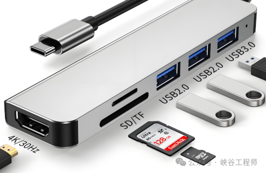
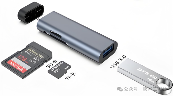
The USB interface, with its plug-and-play versatility and strong compatibility, has almost become the connection bridge for all electronic devices, from keyboards and mice to external hard drives and webcams. However, almost all high-resolution cameras use the MIPI interface instead of the convenient USB. Wouldn’t it be easier to connect all peripherals through a HUB at the USB interface?
1. Purpose of Interface Design
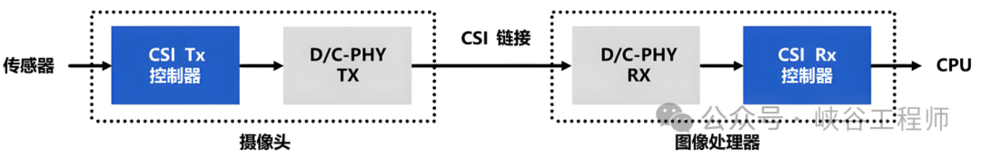
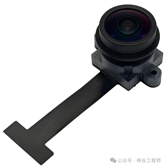
1. MIPI Interface
The core goal of the MIPI interface is to design a low-power, highly integrated, and compact dedicated interface standard for mobile terminals such as smartphones and tablets. It has formed a comprehensive interface system covering camera (CSI), display (DSI), audio (AIF), storage (SLIMbus), and more.
The design logic of MIPI is primarily developed for mobile scenarios:
-
Low Power Consumption: With limited battery capacity, the interface must minimize standby and operational power consumption while ensuring transmission rates;
-
Compact Size: Internal space is precious, so the interface must reduce pin count and physical dimensions;
-
High Integration: SoC (System on Chip) must directly integrate the interface controller to avoid additional chips that increase cost and complexity;
-
Anti-Interference: The internal electromagnetic environment of products is complex, including CPUs, RF modules, batteries, etc., so the interface must have strong anti-interference capabilities.
2. USB Interface
The purpose of the USB interface is to serve as a universal connection solution. Its core goal is to address the complexity of connecting different devices. By providing a unified interface standard, almost all peripherals such as keyboards, mice, printers, and external hard drives can be plug-and-play. USB has evolved from USB 1.0 to USB4, becoming the most widely used universal interface standard globally.
The design logic of USB emphasizes:
-
Universality: Supports a vast array of device types such as storage, audio/video, input/output, etc., with protocols that must be compatible with different data types;
-
Ease of Use: Plug-and-play and hot-swappable, allowing users to connect without specialized knowledge;
-
Standardization: Unified cables, interfaces (Type-A/Type-C), and protocol specifications reduce costs across the industry chain.
2. Transmission Rate
USB 2.0 has a theoretical bandwidth of 480 Mbps, while the latest USB 3.2 Gen2x2 has a theoretical bandwidth of 20Gbps. The latest version of MIPI CSI-2, CSI-2 v2.0, supports a single lane of 2.5Gbps, and with four lanes, it can reach 10Gbps. From a bandwidth perspective, USB 2.0 is not suitable for high-resolution cameras. Although USB 3.0’s 20Gbps seems to outperform MIPI, in practical applications, the effective data transmission requirements of cameras are far below the theoretical bandwidth.
While USB 3.0’s 20Gbps bandwidth is higher, higher bandwidth also means higher power consumption and cost. For mobile devices, MIPI’s bandwidth perfectly matches the camera’s needs, while USB requires additional circuitry, such as high-speed PHY chips, to support it, increasing power consumption and design complexity.
3. Power Consumption
Power consumption is a critical concern for mobile devices, making power control of interfaces essential.
-
MIPI CSI-2 uses differential signaling (D-PHY) and dynamic clock management technology to adjust power consumption based on data volume.
-
When the camera is in idle standby mode, MIPI can enter a low-power mode (LPM), requiring only a very low microamp current.
-
During data transmission, D-PHY intelligently switches between high-speed and low-power modes to further reduce energy consumption.
In contrast, USB interface power consumption control is more passive:
-
Even without data transmission, the USB interface must maintain a 5V power supply, unlike MIPI, which can enter deep sleep.
-
High-speed USB PHY chip power consumption is higher, adding extra pressure on battery life.
4. Physical Interface Design
USB 3.0 requires 8 wires for power and ground configuration, while MIPI CSI can choose the number of channels based on bandwidth requirements, making the design more flexible. The specific differences are shown in the table below:
| Feature | USB 2.0 | USB 3.2 Gen 1×1 | MIPI CSI-2 |
| Main Use | General Peripheral Connection | High-Speed Peripheral Connection (Storage, Video, etc.) | Embedded Device Camera/Image Sensor Interface |
| Data Line Count | 2 (D+, D-) | 8 (including VBUS/GND, etc.) | Expandable (1~8 channels): |
| D+, D- (USB 2.0 Compatible) | 1 pair of differential data lines (Dp, Dn) | ||
| SSRX+, SSRX- (Receiving) | 1 pair of differential clock lines | ||
| SSTX+, SSTX- (Sending) | |||
| Signal Type | Differential Signal | Differential Signal | Differential Signal |
| Transmission Direction | Half-Duplex | Full-Duplex | Unidirectional |
| Clock Mechanism | No Dedicated Clock Line | No Dedicated Clock Line | Dedicated Differential Clock Channel |
| Control/Configuration Line | No Dedicated Line | No Dedicated Line | I2C (SCL, SDA) for Sensor Configuration and Control |
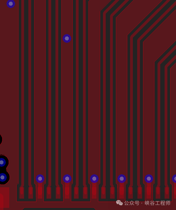
5. Design
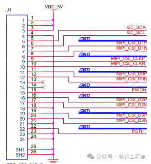
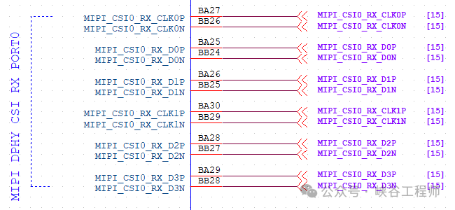
1. MIPI CSI Interface
-
Impedance Control: D-PHY requires a differential impedance of 100Ω±10%. When using stripline stacked design, the effect of the dielectric constant must be calculated.
-
Length Matching: The internal deviation of data pairs should be <5ps (approximately 0.75mm), and the deviation between clock and data groups should be <1ns.
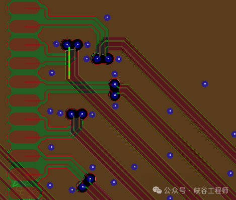
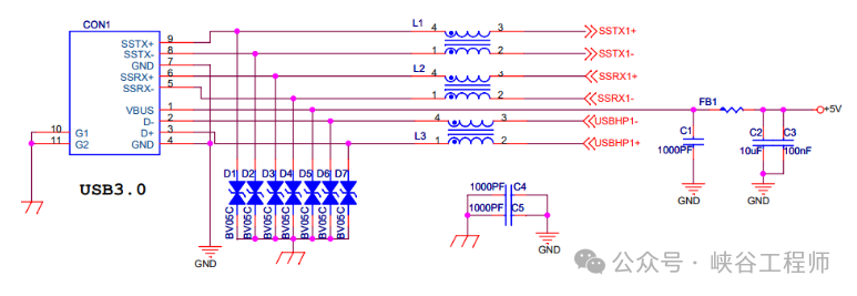
2. USB Interface
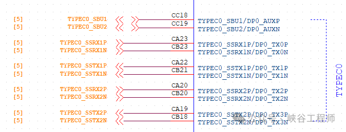
-
Type-C Compatibility: CC pins must be configured with a 5.1kΩ pull-down resistor.
-
High-Speed Signal Processing: USB 3.0 differential pair impedance control is at 90Ω.
-
Avoid more than 3 vias per 10mm routing.
-
Power Management: VBUS must be configured with at least a 47μF large capacitor.