Click the blue text
Follow us
1. Introduction to GMSL
GMSL: Gigabit Multimedia Serial Link is a high-speed serial interface introduced by Maxim, suitable for the transmission of video, audio, and control signals, using 50Ω coaxial cables or 100Ω shielded twisted pair cables, with transmission distances of up to 15m or more.
The characteristic of GMSL technology is to convert parallel data into serial data for transmission, and then decode the serial data back into parallel data at the receiving end. Its advantages include: high speed, long distance, and strong anti-interference capability. Currently, communication protocols based on the GMSL architecture can achieve a maximum single-channel rate of 6Gbps (for reference, USB3.0 only achieves 2.5Gbps), and it is expected to have increasingly widespread applications in the future. Taking ADAS cameras as an example, generally speaking, cameras not only send captured image data externally but also send frame synchronization signals, pixel clocks, and other information, as well as power supply, etc. Therefore, they require a parallel bus composed of many signal lines. As mentioned earlier, parallel buses do not have advantages in high-speed data transmission, so we need to merge these parallel signals into serial signals and transmit them at a higher frequency.
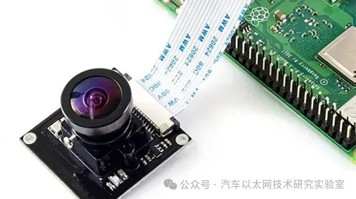 The birth of GMSL technology is to solve the problem of converting parallel data to serial data and then restoring serial data back to parallel data. GMSL is a type of SerDes, which stands for Serializer/Deserializer. The serial-deserialization of SerDes can be implemented through analog circuits or FPGAs. However, in the commercial field, for cost-effectiveness considerations, independent IC chips are often used to achieve this function, and GMSL is a collection of serial-deserialization chips developed by Maxim.
GMSL technology has undergone a long development period, with the first generation of GMSL starting in 2003, supporting a maximum transmission rate of 3Gbps, sufficient for transmitting 1 million to 3 million pixels (1080p/30fps) of video stream data. After 2017, GMSL2 technology emerged, with transmission bandwidth increased to 6Gbps, easily transmitting 8 million pixels (4K/30fps) of video stream data.
GMSL Serializer-Deserializer
Maxim currently offers two generations of GMSL products, namely GMSL1 and GMSL2, with some GMSL2 products being compatible with GMSL1. Common GMSL serializer-deserializer chips are shown in Table 1. Devices compatible with GMSL1/2 can connect to both GMSL1 and GMSL2. For example: a) MAX9296 deserializer can connect to both MAX96701 (GMSL1) and MAX96717 (GMSL2); b) MAX9295A serializer can connect to both MAX9286 (GMSL1) and MAX96712 (GMSL2); in addition, GMSL1 serializers cannot connect to GMSL2 deserializers, and vice versa.
1 GMSL Serializer-Deserializer Configuration Table
From the SoC perspective, if we ignore the serialization-deserialization process, we can consider the SoC as directly connected to the camera sensor. Since the transmission delay of GMSL coaxial lines is almost negligible (in the ns range), it effectively extends the transmission distance of high-speed parallel signals (MIPI/I2C/CLK, etc.) that were originally limited to short distances, achieving true high bandwidth, low latency, and long-distance data transmission.
GMSL Data Access Methods1.
The NVIDIA Jetson Xavier platform, represented by the Jetson Xavier, typically does not have a direct GMSL interface but provides MIPI signal interfaces. Therefore, it requires an external deserialization board to implement the connection, as illustrated in the following configuration. The hardware connection method is shown in Figure 4, where the camera includes a sensor (IMX390) and a serializer (MAX9295), and two cameras are connected via GMSL Link coaxial cable (Coax Cable) to the adapter board (MAX9296 Deserializer Board), which is then connected to the CSI Port of the Jetson Xavier development board via a ribbon cable (MIPI White Cable).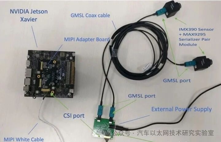
The hardware architecture is shown in Figure 5: the sensor (IMX390) interface is MIPI-CSI, with a data format of 1080p/30fps/RAW12, with each camera paired with one MAX9295 serializer (Serializer) and two GMSL Links connected to the MAX9296 deserializer, which connects to the CSI port of the Jetson (taking Port A as an example).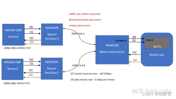 The driver layer structure is shown in Figure 6, where the top layer of the driver is the v4l2 architecture, which is a general camera driver framework under the Linux system. The middle layer is the sensor driver, used to control the switching of the video stream and set image parameters, etc. The bottom layer is the MAX9295/9296 driver, responsible for establishing the data link.
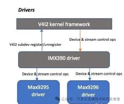
The sensor driver program will configure the parameters of the serializer-deserializer during device boot, establishing the data streaming pipeline. Once the data link is established, it is possible to configure the register parameters of the serializer, deserializer, and sensor separately, controlling their operating modes or performing data stream switching operations, etc.


*Disclaimer: This article is original or forwarded by the author.If any party’s intellectual property rights are inadvertently infringed, please inform us for deletion.The above images and text are sourced from the internet; if there is any infringement, please contact us in a timely manner, and we will delete it within 24 hours.The content of the article represents the author’s personal views,The Automotive Ethernet Technology Research Laboratory reprints it only to convey a different perspective and does not represent theAutomotive Ethernet Technology Research Laboratory‘s endorsement or support of this view. If there are any objections, please feel free to contact the Automotive Ethernet Technology Research Laboratory.