Abstract:This paper introduces the main technical performance requirements of RS-485 bus cables for communication in the 90 ℃ tower solar photothermal power generation mirror field. It elaborates on the material selection and production process control of heat-resistant, cross-linked polyethylene insulated RS-485 bus cables used in the 90 ℃ tower solar photothermal power generation mirror field. Through structural design and calculation examples of the main electrical performance of RS-485 bus cables for tower solar photothermal power generation mirror field communication, key parameter design, testing principles, and testing methods are explained. The RS-485 bus cable for tower solar photothermal power generation mirror field communication was also tested, and results showed that actual measured values met design requirements, satisfying the demand for RS-485 on-site communication in the tower solar thermal power generation mirror field, which has broad application prospects.
Keywords:Solar thermal power generation; Mirror field; RS-485 bus cable; Characteristic impedance; Attenuation; Relative velocity of propagation
Solar energy, as a clean and renewable energy source, plays an important role in energy utilization. Currently, solar photovoltaic power generation and solar thermal power generation have become significant channels for developing and utilizing solar energy. Solar photovoltaic technology in China has matured and achieved commercialization and scalability. However, it is vulnerable to natural conditions such as day and night, weather, etc., leading to difficulties in energy storage, instability of sunlight, and impacts on the power grid, which restricts the progress of photovoltaic power generation to some extent. Solar thermal power generation, with its advantages of heat storage, peak shaving, and continuous power generation, has gradually become a hotspot for development and investment in renewable energy.
Solar thermal power generation includes four methods: trough, tower, dish, and linear Fresnel. Although these four methods differ, they can all be divided into three basic systems for power generation: solar heat collection, heat transfer and exchange, and power generation. The tower solar thermal power generation discussed in this work, also known as centralized solar thermal power generation, utilizes heliostats to focus sunlight on the receiver of the central heat-absorbing tower, heating the heat-absorbing medium molten salt at the top of the tower, converting solar radiation energy into thermal energy, exchanging thermal energy with water to form steam, which then drives a steam turbine for power generation. The tower solar thermal power generation system features a high concentration ratio, high working temperature, short heat transfer distance, low heat loss, and high overall system efficiency, making it suitable for large-scale, high-capacity commercial applications.
However, tower solar thermal power plants occupy a large area, with the solar collection mirror field area ranging from 2 to 10 km². The distance between the heliostat and the receiver is usually between 100 and 1000 m, and each heliostat needs to communicate via RS-485 bus cables. A 50 MW tower solar thermal power plant requires approximately hundreds of kilometers of RS-485 bus cables.
The RS-485 bus cable for communication in the mirror field must meet environmental requirements, such as high temperature resistance up to 90 ℃, low temperature resistance down to -40 ℃, UV resistance, and salt-alkali resistance. This work focuses on the structural design, material selection, and production process control of the RS-485 2×0.35+0.35 mm² bus cable for communication in the mirror field.
1 Main Technical Performance Requirements
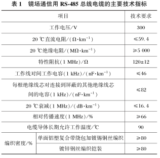
The main technical indicators of the RS-485 2×0.35+0.35 mm² bus cable for communication in the mirror field are shown in Table 1. A comprehensive analysis of the technical indicators highlights that the focus of cable design lies in material selection, cable structure, and electrical performance indicators.
Table 1 Main Technical Indicators of RS-485 2×0.35+0.35 mm² Bus Cable for Communication in the Mirror Field
2 Material Selection and Production Process Control
The conductor material for the RS-485 bus cable used in the mirror field is made of tinned soft copper wire to enhance the corrosion resistance of the cable conductor. The conductor structure is 19×0.16 mm, with 19 strands of tinned soft copper wire arranged in a 1+6+12 configuration, twisted together effectively to reduce the cable conductor’s diameter and resistance. The conductor twisting should be tightly rounded, with a left-handed twist direction and a twist pitch of 10 to 12 mm. The outer diameter of the conductor is controlled within 0.78 to 0.80 mm.
The RS-485 bus cable for communication in the mirror field requires direct burial installation, necessitating improved resistance to lateral pressure. To ensure stable conductor spacing and related performance parameters, solid insulation is utilized. Considering the significant temperature differences in the solar thermal power generation mirror field, high surface temperatures during the day, as well as manufacturing costs and production efficiency, 90 ℃ high-purity hot water silane cross-linked polyethylene material is selected as insulation. This choice enhances the cable’s working temperature, reduces manufacturing costs, and meets electrical transmission performance requirements.
During the insulation extrusion process, strict control of the uniformity of the insulation outer diameter is required to prevent fluctuations and eccentricity in the insulation core’s outer diameter, ensuring uniformity of the cable’s characteristic impedance.
2.3 Cable Formation and Shielding
The RS-485 2×0.35+0.35 mm² bus cable for communication in the mirror field has a three-core structure, where 2×0.35 mm² serves as the working wire pair, and 0.35 mm² serves as the ground wire core. The working wire pair is colored white and orange, while the ground wire core insulation is blue. To ensure the roundness and structural stability of the cable core, the outer diameter of the grounding insulated wire is designed to be consistent with the filling rope. During cable formation, the ground wire core and one filling strip are symmetrically placed on both sides of the two working wire pairs, achieving structural stability and roundness.
To reduce the cable’s capacitance, polypropylene foam tape is used for wrapping and isolation during cable formation. A single-sided aluminum-plastic composite tape with a thickness of 0.05 mm is used for wrapping, along with tinned copper wire woven shielding. The composite tape’s overlap rate is not less than 25%, with the metal side facing out, in contact with the tinned copper wire woven layer. The diameter of the tinned woven copper wire is not less than 0.12 mm, and the weaving density is not less than 80%. A 0.35 mm² tinned soft copper wire is added between the composite tape and the woven layer as a drainage wire for welding terminals or connectors during grounding.
2.4 Isolation Sleeve and Armoring
To prevent cable damage from soil settlement, compression, and other external forces, galvanized steel wire weaving is used to enhance the cable’s compressive and tensile strength. The armoring material differs from the shielding material; to prevent electrochemical corrosion between different metal materials, a layer of PVC sheath with a thickness of 1.0 mm is extruded under the armoring layer for isolation. The heat resistance of the PVC sheath material is consistent with that of the insulation material, and the sheath extrusion process adopts a power frequency spark test to ensure the integrity of the sheath. The diameter of the woven armoring using galvanized steel wire is not less than 0.2 mm, with a weaving density of not less than 80%.
Considering the significant temperature differences, strong UV radiation, and high soil salinity in the northwest, the outer sheath is made of PVC material that is resistant to low temperatures down to -40 ℃, high temperatures up to 90 ℃, salt-alkali resistant, UV resistant, and flame-retardant. The outer sheath of the RS-485 bus cable for communication in the mirror field is generally gray, but can also be selected based on actual needs.
3 Key Structure and Performance Design
The structural schematic of the RS-485 bus cable for communication in the mirror field is shown in Figure 1. The number and diameter of conductors are 19 and 0.16 mm, respectively, with an outer diameter of the twisted conductor being 0.8 mm. The outer diameter of the working wire pair insulation is 2.50 to 2.60 mm, while the diameter of the ground wire core and filling strips is 1.60 to 1.70 mm. After cable formation, a polypropylene foam tape is wrapped, and the shielding layer is formed using a single-sided aluminum-plastic composite tape wrapped with tinned copper wire weaving. The outer diameter of the cable after sheath extrusion is 12.6 to 13.0 mm. Based on the structure of the RS-485 bus cable for communication in the mirror field, calculations of its electrical and transmission performance parameters are conducted to verify whether the structural parameters of this bus cable can meet design requirements.
3.1 Main Electrical Performance Calculations
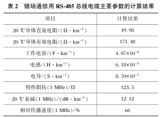
The main electrical performance parameters of the RS-485 bus cable for communication in the mirror field include resistance, inductance, capacitance, conductance, characteristic impedance, attenuation, and relative velocity of propagation. The calculation process has been detailed in related articles, with the main parameter calculation results shown in Table 2.
3.2 Testing Principles and Methods for Characteristic Impedance and Attenuation
The testing methods for other parameters of the cable are specified in standards, while this section mainly introduces the testing principles and methods for characteristic impedance and attenuation.
Table 2 Calculation Results of Main Parameters of RS-485 Bus Cable for Communication in the Mirror Field
3.2.1 Testing Principles and Methods for Characteristic Impedance
The characteristic impedance and attenuation parameters of the RS-485 bus cable for communication in the mirror field are required to be tested at a frequency of 1 MHz. The reference method for characteristic impedance testing is open-end and short-circuit impedance testing, with the following principles. For example, when the cable terminal is open at a frequency of 1 MHz, the impedance at the starting end is tested.
When the cable is short-circuited at the same terminal, the impedance at the same starting end is tested.
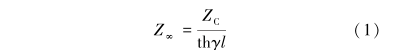
The characteristic impedance of the cable is the square root of the product of the input impedances during open and short circuit tests.
Where: Zc is the characteristic impedance of the cable, Ω; Z∞ is the impedance tested when the cable is open at the same end, Ω; Z0 is the impedance tested when the cable is short-circuited at the same end, Ω; γ is the transmission constant of the cable; L is the length of the cable, km; th is the hyperbolic tangent function.
3.2.2 Testing Methods for Attenuation
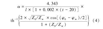
During open-end and short-circuit impedance testing, the phase angles of the open and short-circuit impedances at 1 MHz are measured and calculated according to the formula:
Where: α is the attenuation of the cable at a temperature of 20 ℃, dB·km-1; t is the environmental temperature during cable testing, ℃; φ0 is the phase angle during short-circuit testing of the cable, °; φ∞ is the phase angle during open-circuit testing of the cable, °.
According to the above structure design, material selection, process control, and key performance design, the RS-485 3×0.35+0.35 mm² tinned soft copper conductor solid cross-linked polyethylene insulated field bus cable was tested, and its performance met the process design requirements. Specific test results are shown in Table 3.
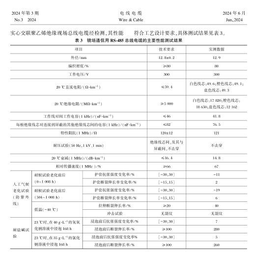
This work designs a mirror field communication RS-485 3×0.35+0.35 mm² bus cable, achieving technical requirements for cables used in tower solar photothermal power generation mirror fields in terms of structural dimensions, electrical performance indicators, high-temperature resistance, low-temperature resistance, and environmental resistance. The insulation uses 90 ℃ high-purity hot water silane cross-linked polyethylene material, which raises the working temperature of the conductor from 70 ℃ to 90 ℃, improving the heat resistance of the RS-485 bus cable insulation and meeting the requirements of the solar thermal power generation site with significant day-night temperature differences and high daytime temperatures. The cable core uses galvanized steel wire weaving for armoring, and solid insulation further enhances the cable’s compressive and tensile strength, meeting the requirements for direct burial installation in soil. The cross-linking of the insulation uses hot water or steam cross-linking methods, which also reduces the manufacturing production costs.
Through the design of the RS-485 3×0.35+0.35 mm² bus cable for communication in the tower solar photothermal power generation mirror field, a reference for the selection of RS-485 bus cables for tower solar photothermal power generation mirror fields is provided. At the same time, a further understanding of the structural design and electrical transmission performance parameters of the RS-485 bus cable for communication in the mirror field can serve as a reference for the structural design of other RS-485 bus cables.
[1] Li Qionghui. Current Status and Market Prospects of Solar Thermal Power Generation [J]. Electrical Industry, 2011(8):28-31.
[2] Yuan Weidong. Current Status and Prospects of Solar Thermal Power Generation at Home and Abroad [J]. Power and Energy, 2015(8):487-490.
[3] Wang Hailing, Cai Qingqing, Zhang Hongyan. Design of 77 Ω Data Bus Cable for Aerospace Applications [J]. Optical Fiber and Cable and Its Application Technology, 2019(2):22-25.
[4] Zheng Yudong. Communication Cables [M]. Beijing: Mechanical Industry Press, 1982.
[5] National Standardization Management Committee of China. Testing Methods for Communication Cables: GB/T5441-2016[S]. Beijing: China Standards Press, 2016.
Source:
Originally published in the third issue of “Wires and Cables” in June 2024
Authors and Affiliations:
1. Wang Hailing: Anhui Xinke Cable Group Co., Ltd., Wuwei 238300; Anhui Tiexin Optoelectronic Technology Co., Ltd., Wuwei 238300.
2. Wang Yi: China Academy of Railway Sciences Corporation Limited Standard & Metrology Research Institute, Beijing 100081.
3. Zhang Hongyan: Anhui Zongheng Hi-Tech Cables Co., Ltd., Hefei 230051.